Systems and methods for controlling hydrogen generation

a technology of hydrogen generation and control system, applied in chemical/physical processes, chemical apparatus and processes, inorganic chemistry, etc., can solve problems such as the complicated use of hydrogen gas in the general publi

Inactive Publication Date: 2006-10-12
MILLENNIUM CELL
View PDF12 Cites 54 Cited by
  • Summary
  • Abstract
  • Description
  • Claims
  • Application Information

AI Technical Summary

Benefits of technology

[0005] The present invention provides systems and methods for monitoring at least one and preferably at least two system parameters (such as temperature or pressure within the system, or pressure at two different locations in the system) of a hydrogen generation system and / or controlling hydrogen generation from a fuel solution by regulating the flow rate of the fuel solution to the reactor. By “two system parameters” herein we also mean to include a single variable, such as pressure, measured at two different locations. Among the parameters that may be sensed and used in the control sequences herein are, for example, pressure, temperature, volume, flow rate, and concentration of species such as H2, CO and CO2 in the system. When a single parameter is detected, preferably that parameter is temperature. When a plurality of parameters are detected for the control methods herein, such parameters are preferably temperature and pressure, or pressures at two distinct locations, or pressures at two distinct locations and temperature. Temperature may be measured at any place in the system, but preferably in the reactor.

Problems solved by technology

Although hydrogen is the fuel of choice for fuel cells, its widespread use is complicated by the difficulties in storing the gas.

Method used


Image

  • Systems and methods for controlling hydrogen generation
  • Systems and methods for controlling hydrogen generation
  • Systems and methods for controlling hydrogen generation

Examples


example 1

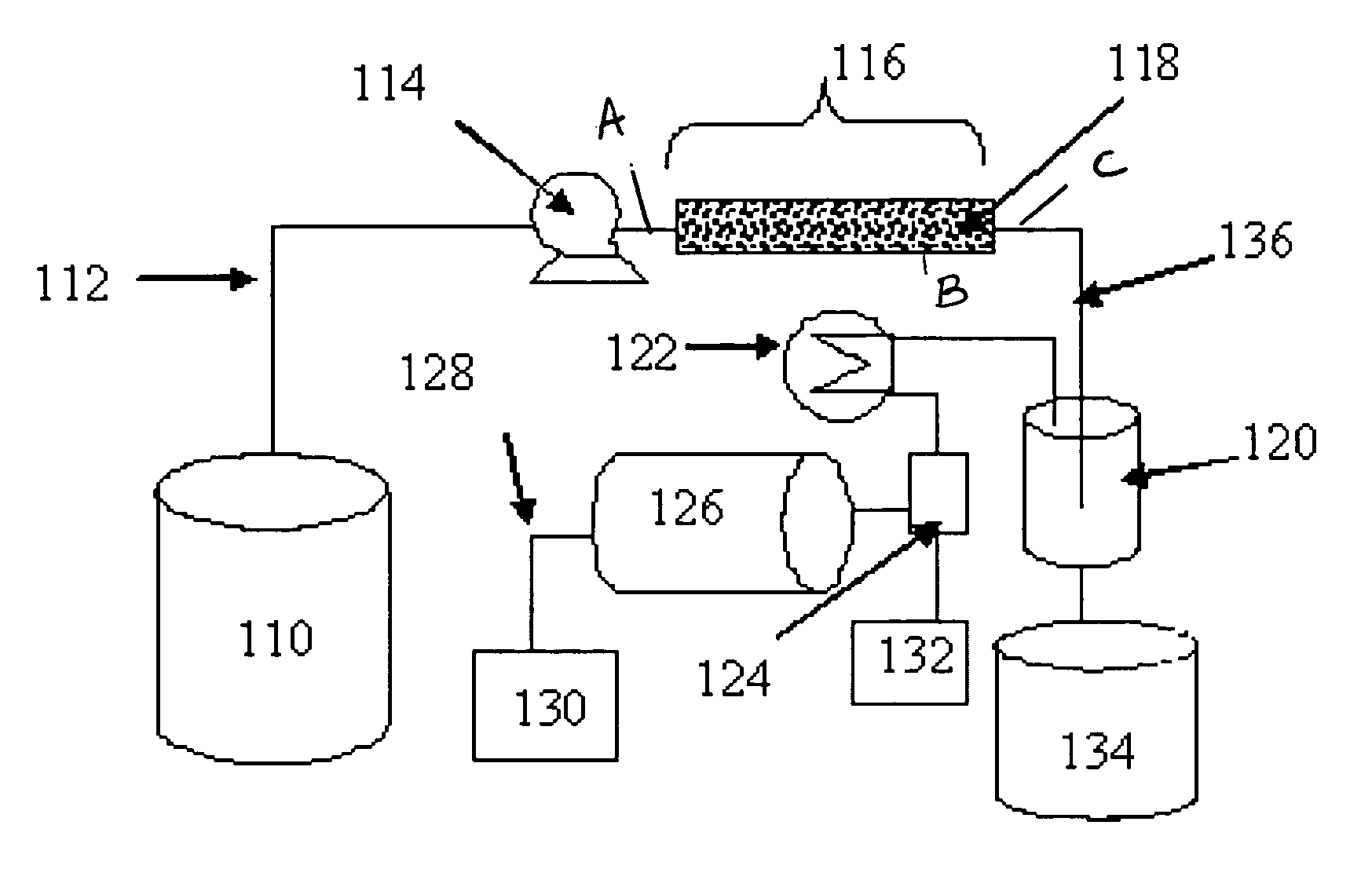
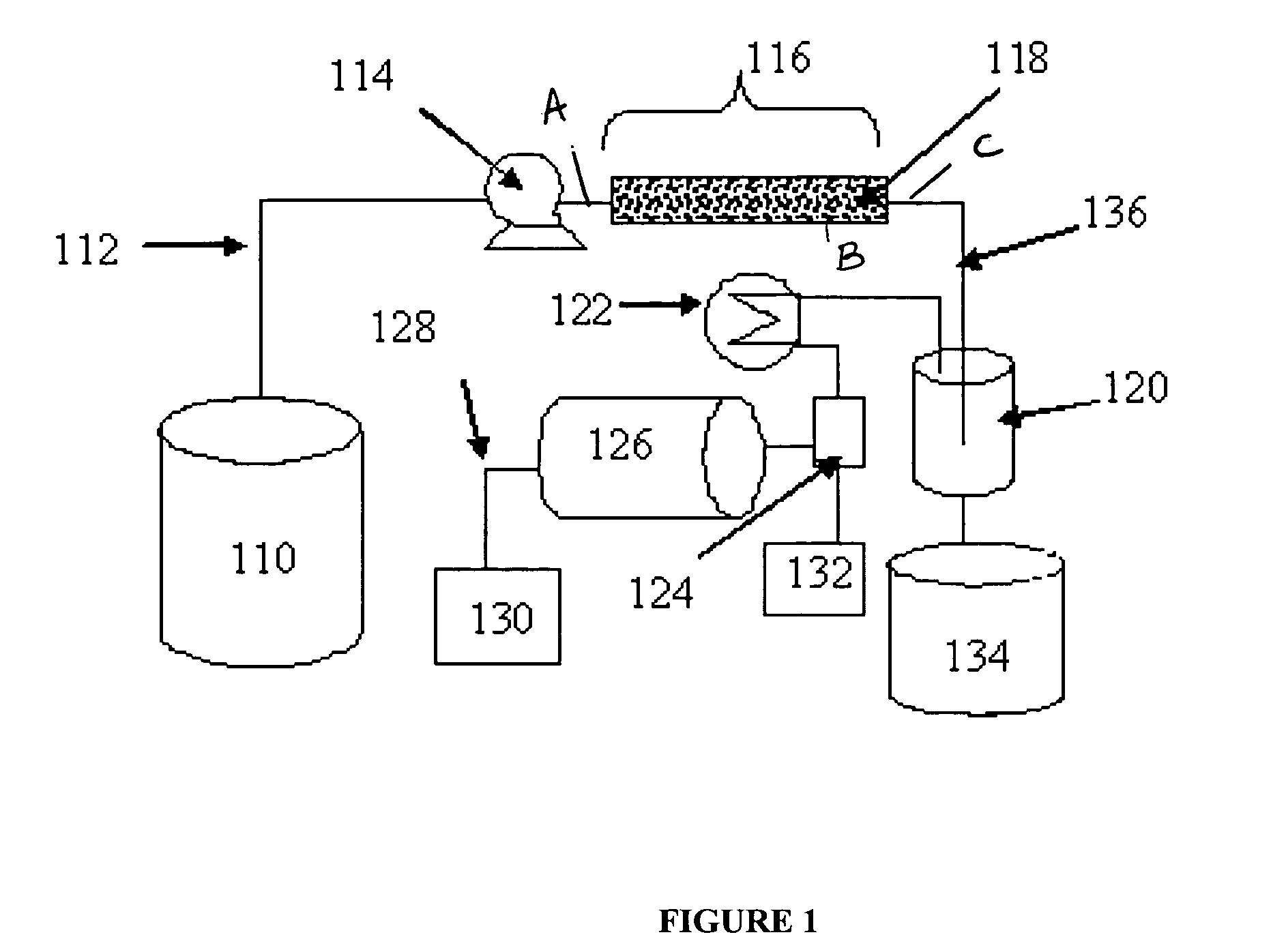
[0037] A hydrogen generation system as shown in FIG. 1 was controlled by a method according to the present invention and used to generate hydrogen for a fuel cell requiring hydrogen delivered at 25 psig and a gas flow rate of about 10 standard liters per minute. Referring to FIG. 1, the borohydride fuel solution is metered from storage tank 110 through fuel line 112 using fuel pump 114 and delivered into reaction chamber 116 comprising catalyst bed 118 where it undergoes the reaction of Equation (1) to generate hydrogen and a borate salt. The product stream is carried to a gas liquid separator 120 via conduit line 136 and the hydrogen gas is processed through a heat exchanger 122 to cool the gas stream to near ambient temperature and a condenser 124 to remove water from the hydrogen gas stream. Condensed water is collected in water tank 132. The hydrogen gas is fed to a ballast tank 126 and then carried through the hydrogen conduit line 128 to feed a fuel cell 130. The liquid borate...

example 2

[0041] The reaction chamber of the system described in Example 1 was equipped with inlet (Sensor A) and outlet (Sensor C) pressure and temperature (Sensor B) sensors that provided input to a controller element. The system was automatically controlled according to the method illustrated in FIG. 3. The controller received system pressure (PA and PC) readings at defined intervals in Step 201. The PA readings were compared to the Pressure LUT (Table 1A) to determine a flow rate (FP) for the fuel pump in Step 203. The difference in pressure determined in Step 205 was compared to a set point in Step 207. If the pressure exceeded the set point, the fuel pump was immediately signaled to stop feeding fuel to the reactor. If the pressure difference was below the set point, the controller determined the fuel flow by the comparison of fuel flow rates determined by the temperature and pressure lookup tables as described in Example 1 (Steps 209 to 215) to determine the maximum flow rate (FP′) for...


PUM

PropertyMeasurementUnit
outlet pressureaaaaaaaaaa
pressureaaaaaaaaaa
temperatureaaaaaaaaaa

Abstract

Systems and methods are disclosed for monitoring at least two system parameters (such as system temperature or pressure, or system pressure at two different locations) of a hydrogen generation system and controlling hydrogen generation from a fuel solution. The system comprises a hydrogen generator having a fuel chamber for a liquid fuel, a reactor chamber where the fuel undergoes a reaction to produce hydrogen, and at least two sensors in communication with the reactor chamber, the sensors measuring at least two system parameters of the hydrogen generator. The methods include control sequences for controlling the fuel flow rate to the reactor based on the sensed parameters.

Description

[0001] This application claims the benefit of U.S. Provisional Application Ser. No. 60 / 647,393, filed Jan. 28, 2005, the entire disclosure of which is incorporated herein by reference.FIELD OF THE INVENTION [0002] The invention relates to systems for generating hydrogen gas from reformable fuels and to methods for monitoring and controlling hydrogen generation. BACKGROUND OF THE INVENTION [0003] Although hydrogen is the fuel of choice for fuel cells, its widespread use is complicated by the difficulties in storing the gas. Many hydrogen carriers, including hydrocarbons, metal hydrides, and chemical hydrides are being considered as hydrogen storage and supply systems. In each case, specific systems need to be developed in order to release the hydrogen from its carrier, either by reformation as in the case of hydrocarbons, desorption from metal hydrides, or catalyzed hydrolysis of chemical hydrides. [0004] Various hydrogen generation systems have been developed for the production of h...

Claims


Application Information

Patent Timeline
Patent Type & Authority Applications(United States)
IPC IPC(8): C01B3/24
CPCB01J7/02B01J19/0006B01J2219/00063B01J2219/00065B01J2219/00164B01J2219/002Y02E60/362B01J2219/00231C01B3/065C01B2203/066C01B2203/1619C01B2203/1633C01B2203/169B01J2219/0022Y02E60/36
Inventor SPALLONE, JOHNMOHRING, RICHARD M.EASON, IANMOLTER, ROBERTBERRY, GRANTFENNIMORE, KEITH A.
Owner MILLENNIUM CELL
Why Eureka
Try Eureka