Method and apparatus for producing thin magnesium based alloy plate

a technology of magnesium alloy and manufacturing method, which is applied in the direction of chemistry apparatus and processes, metal rolling arrangements, metal founding, etc., can solve the problems of inability to effectively manufacture products by plastic working, inability to use casting molds to mold magnesium, and inability to establish a presence in the market for applications of magnesium. , to achieve the effect of effective formation, excellent workability and deterioration of productivity

Active Publication Date: 2006-10-12
GONDA METAL IND
View PDF5 Cites 6 Cited by
  • Summary
  • Abstract
  • Description
  • Claims
  • Application Information

AI Technical Summary

Benefits of technology

[0018] With the above arrangement, since the magnesium metal plate member used in the rolling roll section has a temperature suitable for rolling similarly to the magnesium metal thin plate manufacturing method described above, it is possible to deform the plate member to a thin plate by applying pressure thereto at a desired draft without concern for breakage. That is, since the heat used in casting to form the plate member is utilized, it is not necessary to produce heat energy for rolling again, which permits the effective production of the magnesium metal thin plate.
[0019] Further, it is preferable that the casting roll section include at least a casting lower roll for causing the molten metal stored in the molten metal bath to solidify and to adhere around the roll surface thereof and drawing out the molten metal to the outside of the molten metal bath by the rotational force thereof, a casting upper roll for molding the molten metal drawn out to the outside of the molten metal bath by pressing the solidified surface thereof downward by means of the casting lower roll, and a rotational drive unit for rotating each of the casting lower roll and the casting upper roll and that the temperature of the roll surfaces of the casting lower roll and the casting upper roll can be adjusted, and the gap between the casting lower roll and the casting upper roll can be changed. With the above arrangement, a temperature and a thickness that are suitable for rolling can be freely set to a plate member to be cast, thereby the plate member can be effectively formed.
[0020] In addition, it is preferable in the magnesium metal thin plate manufacturing apparatus that the angle between an imaginary line connecting the rotating shaft of the casting lower roll and the rotating shaft of the casting upper roll and a vertical line (the angle is called a roll angle α) be adjusted. When the angle α departs from a predetermined range, the magnesium metal plate member having been cast is liable to be exfoliated or broken because stress remains in the metal structure of the plate member, thereby productivity is deteriorated. Further, when various magnesium metals having a different composition or a different thickness are applied, optimum conditions for them can be easily set by permitting the angle between the pair of rolls to be adjusted, by which an apparatus excellent in workability can be realized.

Problems solved by technology

Incidentally, heretofore, magnesium metal products are manufactured by die cast and thixotropic molding (injection molding), and it is difficult to effectively manufacture the products by plastic working.
Accordingly, magnesium cannot be molded without using a casting mold, and thus it is applied only to limited products.
That is, at present, magnesium cannot establish a presence in the market in the application thereof to products for various uses made by plastic working because a technology for effectively manufacturing a magnesium metal thin plate has not been established.
Further, in the manufacture of the magnesium metal products described above, a lot of unnecessary products such as runner channels and the like are made in the process of molding magnesium in a metal mold, from which problems arise in that the yields of materials are deteriorated and that gas pockets are formed in molded magnesium products by gas bubbles involved therein.
Since it means that the plate member cannot be deformed to a desired thickness that the draft is limited as described above, it cannot be said that the above method is excellent in productivity.
However, an enormous amount of heat energy is consumed to execute the hot rolling or hot extrusion, from which a technical problem arises in that productivity is bad.
Since the magnesium molten metal, in which the solid phase and a liquid phase coexist as described above, has high viscosity, the molten metal is liable to be solidified in a nozzle for supplying it to the pair of casting rolls, and thus there is a large possibility that the nozzle is clogged by the molten metal.
Accordingly, this method also has a technical problem in that yields in production are low and productivity is bad.

Method used


Image

  • Method and apparatus for producing thin magnesium based alloy plate
  • Method and apparatus for producing thin magnesium based alloy plate
  • Method and apparatus for producing thin magnesium based alloy plate

Examples


first embodiment

Manufacturing Apparatus of First Embodiment

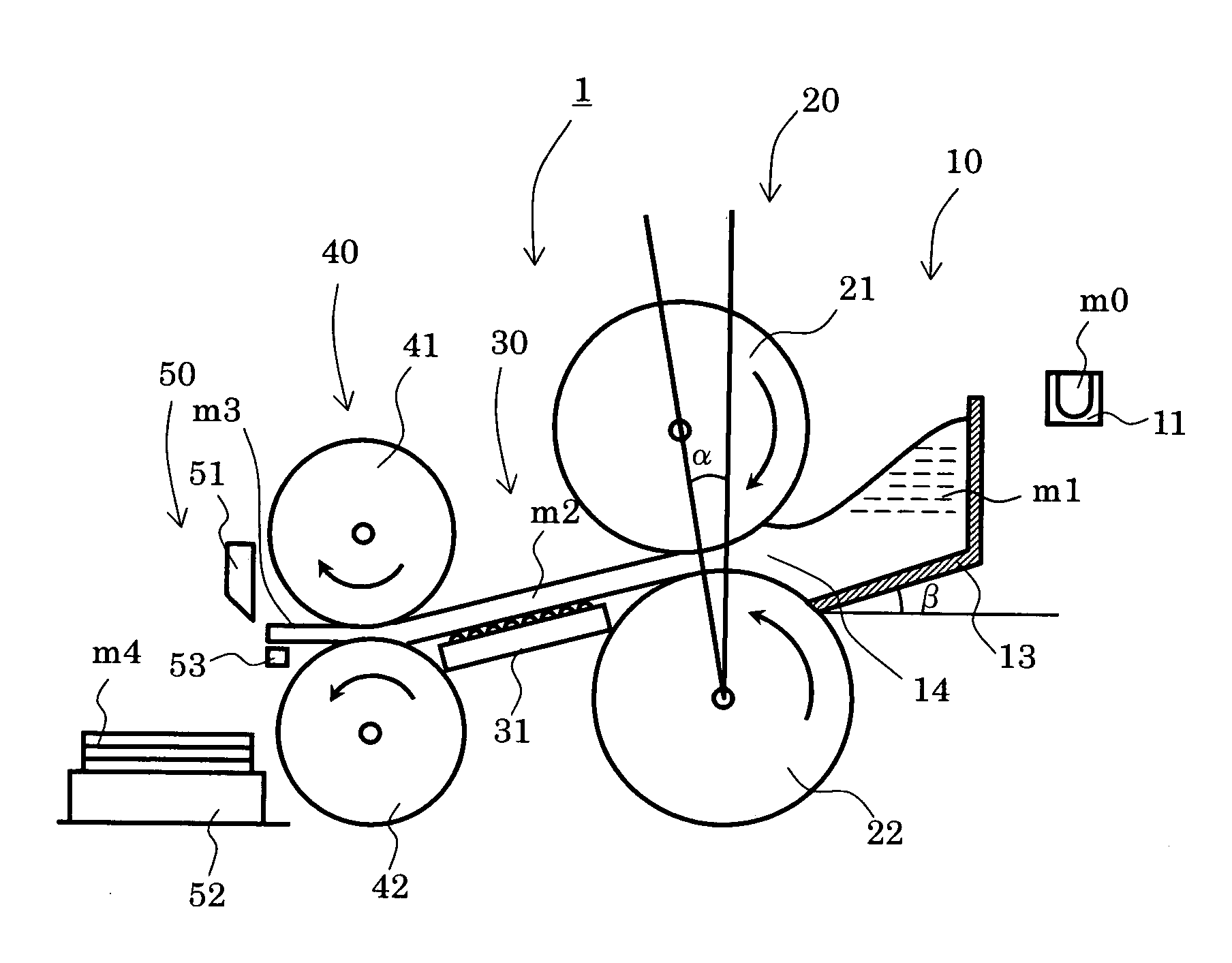
[0029]FIG. 1 is a schematic side elevational view showing the overall arrangement of a magnesium metal thin plate manufacturing apparatus of an embodiment of the present invention.

[0030] Reference numeral 1 in FIG. 1 denotes the magnesium metal thin plate manufacturing apparatus. The magnesium metal thin plate manufacturing apparatus 1 is approximately composed of a molten metal supply section 10, a casting roll section 20, a plate member conveying section 30, a rolling roll section 40, and a working section 50.

(Molten Metal Supply Section)

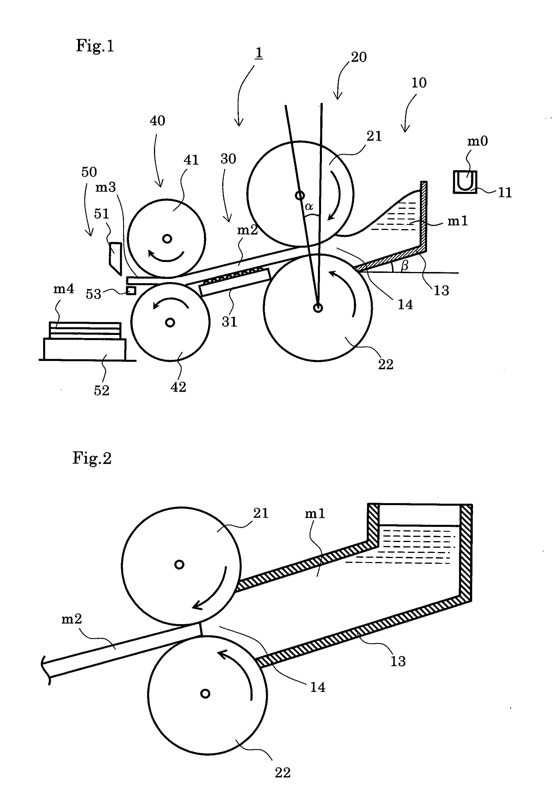
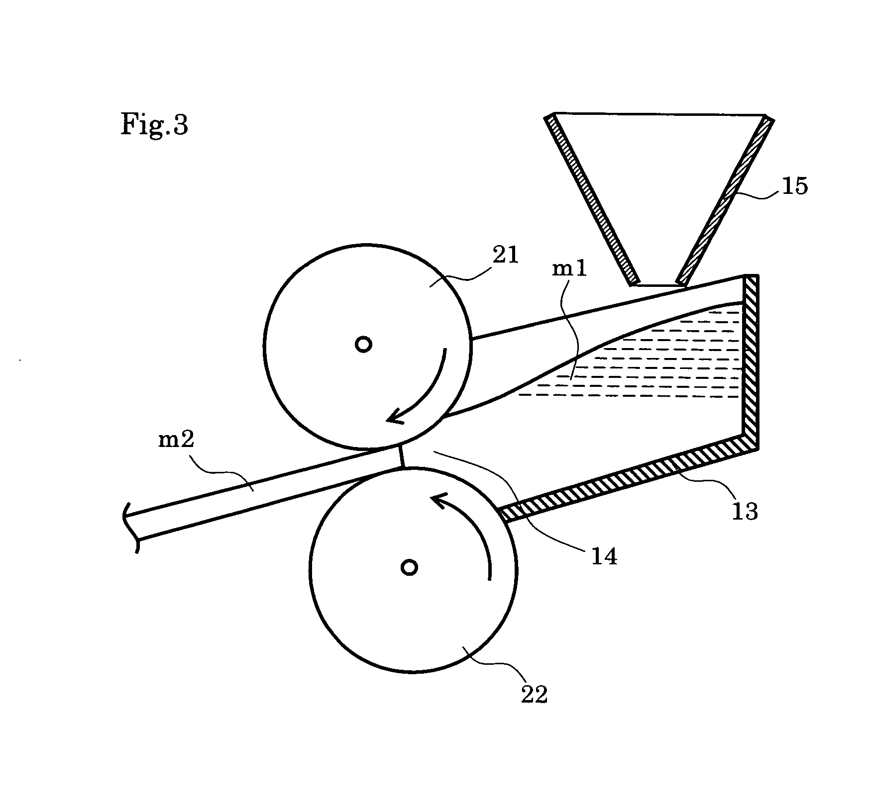
[0031] The molten metal supply section 10 is a mechanism for supplying a magnesium metal melted in a melting device (not shown) to the casting roll section 20 composed of a pair of rolls for casting the magnesium metal in the magnesium metal thin plate manufacturing apparatus 1, and the molten metal supply section 10 is composed of a crucible 11 and a molten metal bath 13.

[0032] The crucible 11 store...

example 1

[0075] A magnesium alloy (composition: AM 60) was melted at 640° C. using the apparatus shown in FIG. 1 and cast using the pair of casting upper and lower rolls 21 and 22 each having a roll diameter of 300 mm and composed of a copper alloy with a gap therebetween set to 2 mm at a roll peripheral speed of 40 m / min with a load per unit length in a roll width direction of 0.6 kN / mm. The temperature of the molten metal was 612° C. when it was introduced to the casting rolls. A plate member having been cast was conveyed using the conveyer belt conveying device and rolled by the rolling rolls, thereby a magnesium alloy plate member having a thickness of 2.5 mm was obtained. The plate member had a flat and smooth surface without ripple mark, interlayer exfoliation, center line segregation and surface roughness.


PUM

PropertyMeasurementUnit
temperatureaaaaaaaaaa
angleaaaaaaaaaa
angleaaaaaaaaaa

Abstract

A magnesium metal thin plate manufacturing method includes at least a casting process of supplying a molten metal obtained by melting a magnesium metal to a molten metal bath, drawing out the molten metal, supplying the molten metal into the gap between a pair of casting rolls composed of at least a pair of casting upper roll and casting lower roll, applying pressure to the molten metal, and casting a plate solidified at a predetermined temperature and having a predetermined thickness, and a rolling process of rolling the cast plate by means of at least a pair of rolling rolls by applying pressure thereto to manufacture a magnesium metal thin plate. With the above arrangement, there can be provided a magnesium metal thin plate manufacturing method and manufacturing apparatus that can effectively manufacture a magnesium metal thin plate by plastic working without requiring a heat energy generation step again in rolling.

Description

TECHNICAL FIELD [0001] The present invention relates to a magnesium or magnesium alloy thin plate manufacturing method and manufacturing apparatus, and to a magnesium or magnesium alloy thin plate manufacturing method and manufacturing apparatus for manufacturing a magnesium or magnesium alloy thin plate by casting and then rolling magnesium or magnesium alloy. BACKGROUND ART [0002] Since magnesium is rich in resources among metals and has gravity smaller than that of aluminum and iron, attention is paid to the application thereof to light-weight parts. Although the actual strength of magnesium is inferior to that of aluminum and iron, it has high specific strength because it is light in weight, and thus it can be used in place of aluminum when the same strength is required. Accordingly, it is expected to apply magnesium to products such as a caring and welfare apparatus and the like the reduction of weight of which is required. [0003] Further, magnesium has such excellent character...

Claims


Application Information

Patent Timeline
Patent Type & Authority Applications(United States)
IPC IPC(8): B22D11/00B22D11/06B21B1/46B21B1/00B21B3/00B22D11/12
CPCB22D11/1206B22D11/0622Y10S164/90B22D11/06B22D11/00B22D11/12
Inventor HAGA, TOSHIOYOSHIDA, KAZUNARIGONDA, YOSHIO
Owner GONDA METAL IND
Why Eureka
Try Eureka