Controllable damping force hydraulic shock absorber

Active Publication Date: 2006-10-12
HITACHI ASTEMO LTD
View PDF10 Cites 72 Cited by
  • Summary
  • Abstract
  • Description
  • Claims
  • Application Information

AI Technical Summary

Benefits of technology

[0009] The present invention has been made in view of the above stated problems. It is an object of the present invention to provide a controllable damping forc

Problems solved by technology

However, when a damping force is controlled only by changing the flow path area of the bypass passage, the following problem arises.
That is, although damping force characteristics can be changed to a large extent in a low piston speed region in which a damping force is dependent on the restriction of an orifice in a fluid passage, damping force characteristics cannot be greatly changed in intermediate and high piston speed regions in which a damping force is dependent on the degree of opening of the damping force generating mechanism (disk valve)

Method used


Image

  • Controllable damping force hydraulic shock absorber
  • Controllable damping force hydraulic shock absorber
  • Controllable damping force hydraulic shock absorber

Examples


Example

[0036] Hereinbelow, description is made in detail with regard to an embodiment of the present invention, with reference to the accompanying drawings.

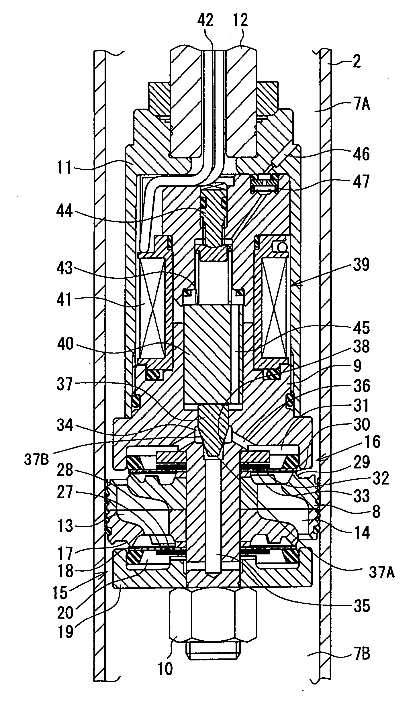
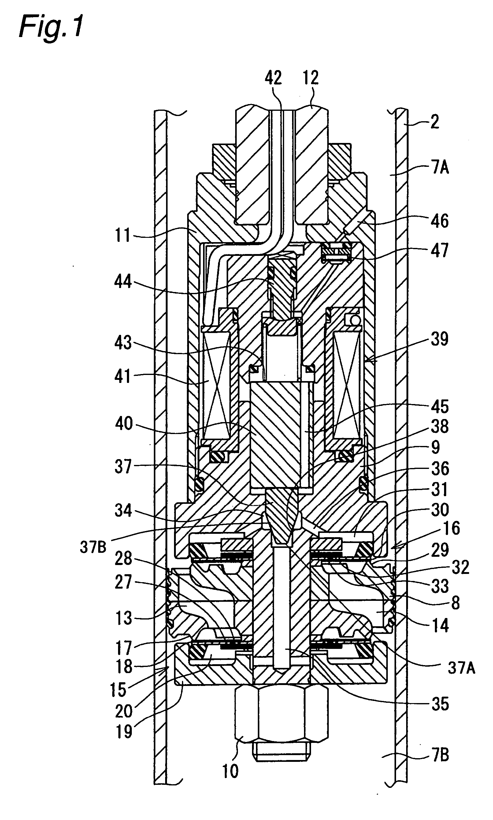
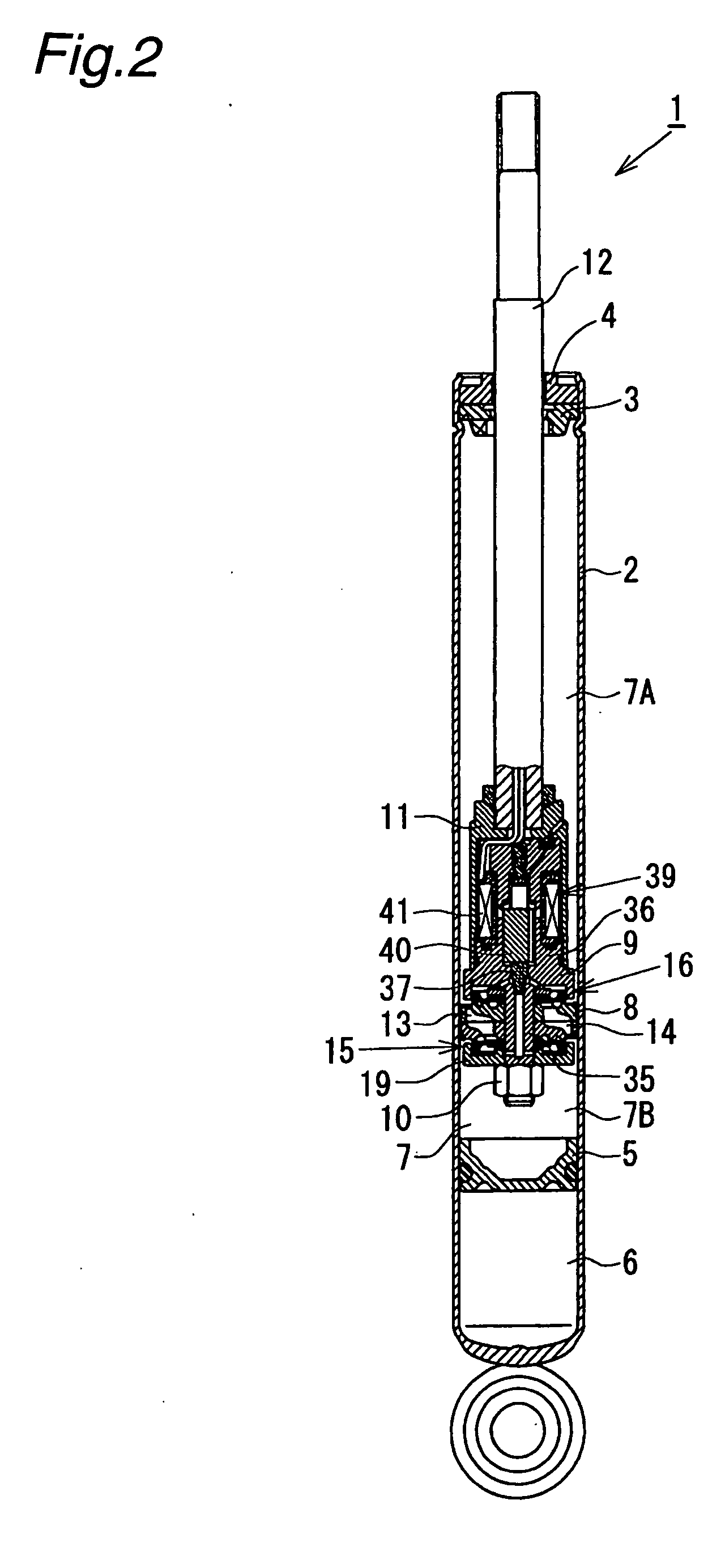
[0037] As shown in FIG. 2, a controllable damping force hydraulic shock absorber 1 in this embodiment comprises a monotube type hydraulic shock absorber. It comprises a cylinder 2 in the form of a circular cylinder having one end closed, with a rod guide 3 and an oil seal 4 being attached to an open end thereof. A free piston 5 is slidably fitted into the cylinder 2 on a side of the closed end thereof. An inside of the cylinder 2 is divided into a gas chamber 6 formed on a side of the closed end of the cylinder 2 and a hydraulic chamber 7 formed on a side of the open end of the cylinder 2. A high-pressure gas is sealed in the gas chamber 6, and a hydraulic fluid is sealed in the hydraulic chamber 7.

[0038] A piston 8 is slidably fitted into the hydraulic chamber 7 of the cylinder 2. By means of the piston 8, an inside of the hydraulic ...


PUM


Abstract

The present invention provides a controllable damping force hydraulic shock absorber comprising a pilot type damping valve having a back-pressure chamber for each of an extension stroke and a compression stroke, which has a simple structure. A piston connected to a piston rod is fitted into a sealed cylinder in which a hydraulic fluid is contained. During an extension stroke of the piston rod, the hydraulic fluid in an upper cylinder chamber flows to a lower cylinder chamber through an extension-side hydraulic fluid passage, an extension-side orifice hydraulic fluid passage, an extension-side back-pressure chamber, an axial hydraulic fluid passage, a radial hydraulic fluid passage, a compression-side back-pressure chamber, an extension-side check valve and a compression-side hydraulic fluid passage. During a compression stroke, the hydraulic fluid in the lower cylinder chamber flows to the upper cylinder chamber through the compression-side hydraulic fluid passage, the compression-side orifice passage, the compression-side back-pressure chamber, the radial hydraulic fluid passage, the axial hydraulic fluid passage, the extension-side back-pressure chamber, the compression-side check valve and the extension-side hydraulic passage. The hydraulic fluid passage for an extension stroke and the hydraulic fluid passage for a compression stroke have some elements in common, thus simplifying a structure of the controllable damping force hydraulic shock absorber.

Description

BACKGROUND OF THE INVENTION [0001] The present invention relates to a controllable damping force hydraulic shock absorber capable of appropriately controlling damping force characteristics. [0002] As a hydraulic shock absorber mounted on a suspension apparatus of a vehicle such as an automobile, there is known a controllable damping force hydraulic shock absorber in which damping force characteristics can be appropriately controlled according to road surface conditions, vehicle running conditions, etc., so as to improve ride comfort and steering stability. [0003] Generally, a controllable damping force hydraulic shock absorber comprises a sealed cylinder in which a hydraulic fluid is contained, and a piston connected to a piston rod is slidably fitted into the cylinder. The piston divides the inside of the cylinder into two chambers. The piston is provided with a main hydraulic fluid passage and a bypass passage which permit communication between the two chambers in the cylinder. Th...

Claims


Application Information

Patent Timeline
IPC IPC(8): F16F9/12
CPCF16F9/3484F16F9/464B60G3/26B60G21/051B60G2200/46B60G2200/4622B60G2206/50B62D17/00
Inventor NAKADATE, TAKAO
Owner HITACHI ASTEMO LTD
Why Eureka
Try Eureka