High frequency heating apparatus
a heating apparatus and high frequency technology, applied in the direction of electric/magnetic/electromagnetic heating, printed circuit non-printed electric components association, semiconductor/solid-state device details, etc., can solve the problems of reducing cost and comparatively high cost, and achieve the effect of minimizing the error of the correlation between input current and reference valu
- Summary
- Abstract
- Description
- Claims
- Application Information
AI Technical Summary
Benefits of technology
Problems solved by technology
Method used
Image

Examples
first embodiment
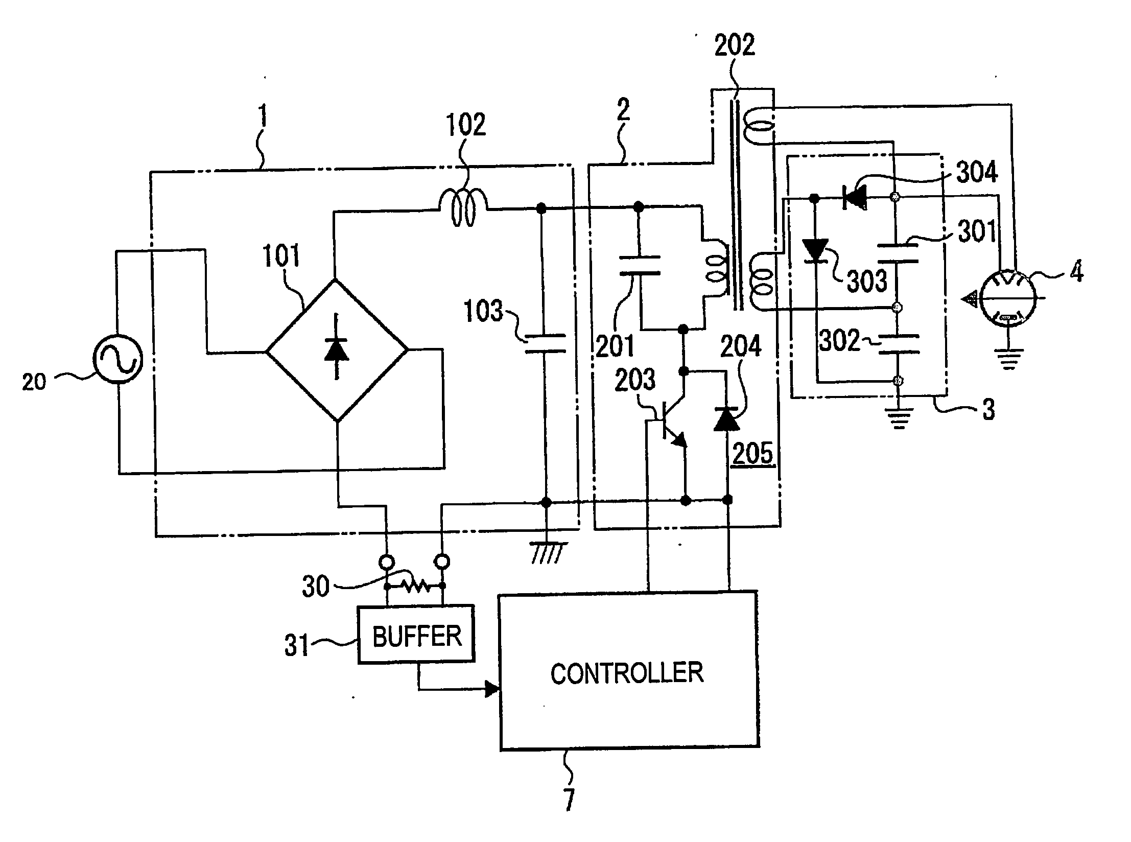
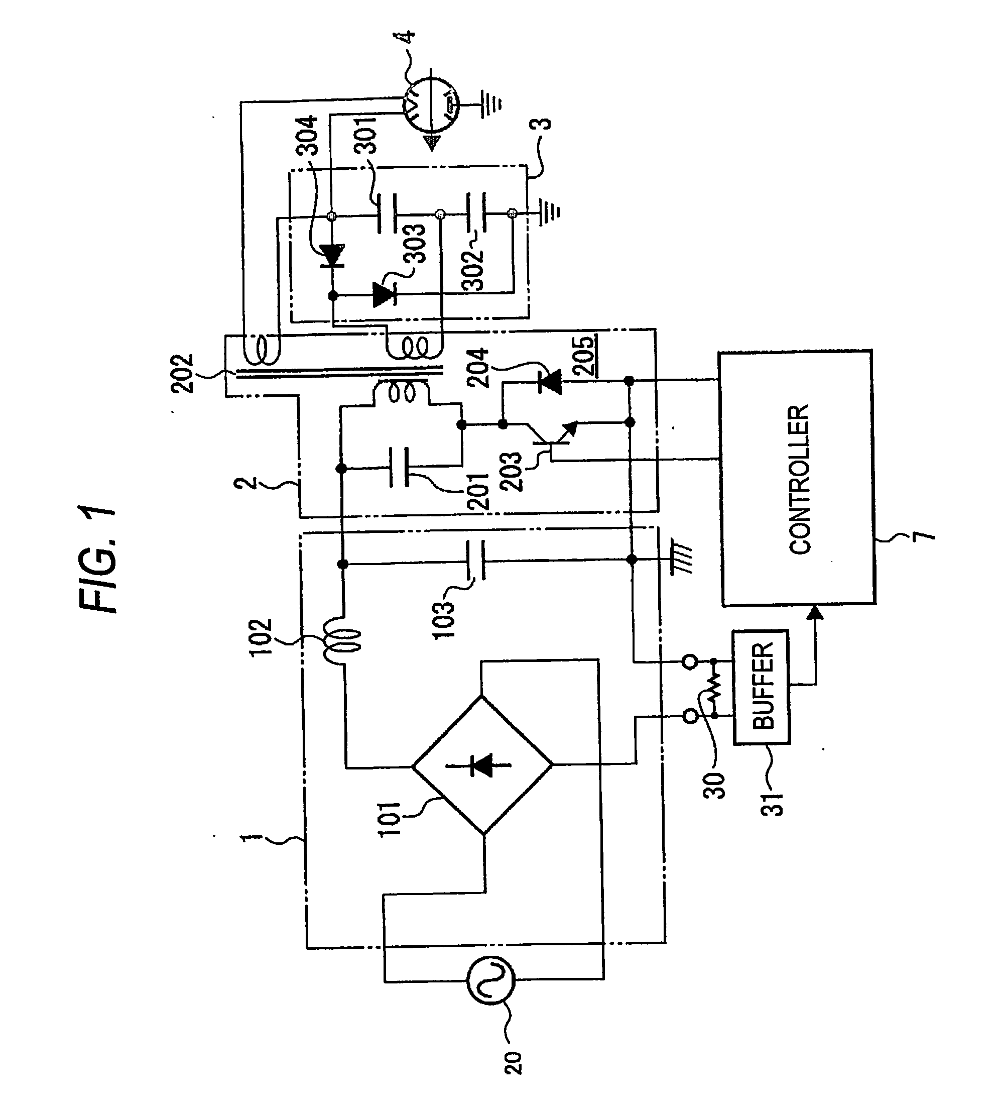
[0063]FIG. 1 is a diagram showing a constitution of a high frequency heating apparatus according to an embodiment of the invention. Further, in the drawing, portions common to those of FIG. 9, mentioned above, are attached with the same notations and an explanation thereof will be omitted.
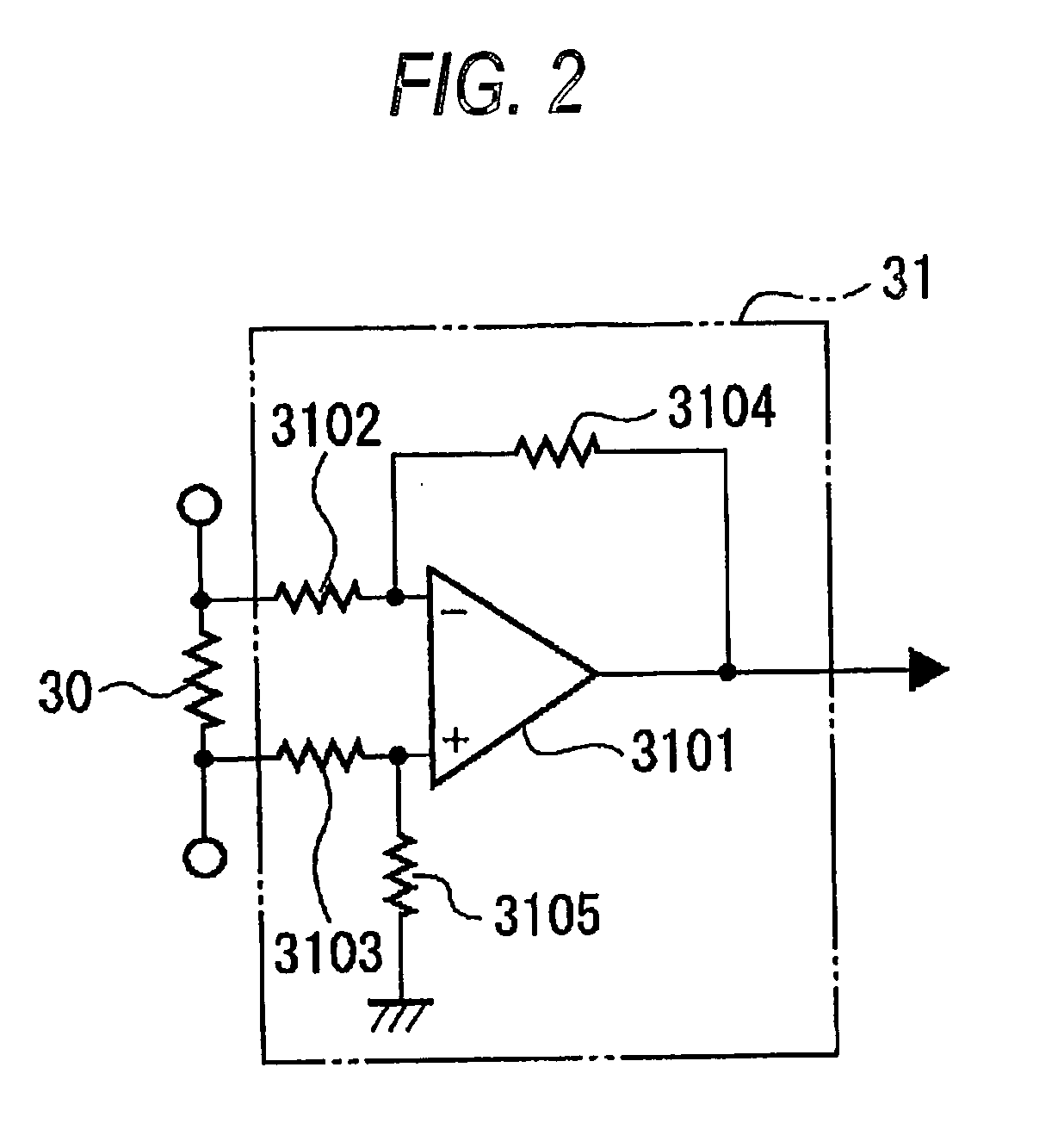
[0064] The high frequency heating apparatus of the embodiment differs from the high frequency heating apparatus of the prior art in including a shunt resistor 30 for detecting an input current and a buffer 31 for taking out a voltage generated at the shunt resistor 30.
[0065] Further, as the shunt resistor 30, a bare resistor wire is used different from a type of being attached to a heat radiating plate or a cement mold type as in the prior art. By using the bare resistor wire, in comparison with the prior art, space saving formation is achieved and a reduction in cost is achieved.
[0066] The shunt resistor 30 is inserted in series with a negative output side terminal of the diode bridge 101 of th...
second embodiment
[0088] A high frequency heating apparatus of FIG. 10 is provided with a cement resistor 50 for lowering a voltage of the direct current output of the unidirectional power source portion 1 to a predetermined voltage between the direct current output end of the unidirectional power source portion 1 and a power source terminal of the control portion 7. In this case, in mounting the cement resistor 50 to a printed board, in order to effectively cool generated heat, the cement resistor 50 is arranged in a direction substantially intersecting with a wind path of cooling wind.
[0089]FIG. 11 is a view showing a state of mounting a portion of the printed board in the high frequency heating apparatus according to the embodiment. Further, FIG. 12 is a view viewing FIG. 11 in an arrow mark Ya direction and on a skewed upper side and FIG. 13 is a view viewing FIG. 11 from the arrow mark Ya direction.
[0090] As shown by FIG. 11, the shunt resistor 30 is arranged on a straight line substantially t...
third embodiment
[0106] An explanation will be given by comparing a constitution which is not provided with a conductive through hole, an eyelet constitution and a constitution of soldering a both face conductive portion with regard to an improvement in current-voltage converting accuracy and an increase in current control accuracy by reducing a change in a resistance value of the shunt resistor having a temperature dependency and also reducing a change in the resistance value by a deterioration thereof simultaneously therewith.
[0107]FIG. 8 is a sectional view showing a constitution which is not provided with a conductive through hole of the printed board mounted with the shunt resistor. FIG. 6 is a sectional view showing an eyelet constitution of the printed board mounted with the shunt resistor. FIG. 7 is a sectional view showing a constitution of soldering a both face conductive portion of the printed board mounted with the shunt resistor.
[0108] According to the constitution which does not use ...
PUM
 Abstract
Description
Claims
Application Information
 - R&D
- Intellectual Property
- Life Sciences
- Materials
- Tech Scout
- Unparalleled Data Quality
- Higher Quality Content
- 60% Fewer Hallucinations
Browse by: Latest US Patents, China's latest patents, Technical Efficacy Thesaurus, Application Domain, Technology Topic, Popular Technical Reports.
© 2025 PatSnap. All rights reserved.Legal|Privacy policy|Modern Slavery Act Transparency Statement|Sitemap|About US| Contact US: help@patsnap.com