Passive entry sensor system

a sensor system and passive entry technology, applied in the field of sensors and applications, can solve the problems of time-consuming and unergonomic, difficult to perform specific actions, and loss or damage of keys, and achieve the effect of rapid assembly of the system

Inactive Publication Date: 2006-10-12
HONEYWELL INT INC
View PDF8 Cites 70 Cited by
  • Summary
  • Abstract
  • Description
  • Claims
  • Application Information

AI Technical Summary

Benefits of technology

[0014] It is an additional aspect of the present invention to provide for an improved passive entry sensor and system which can be utilized with an access control system for allowing access to a vehicle.
[0017] When handle mounted, the sensor can be arranged to provide an electromagnetic radiation beam transmitted either along the length of the handle between opposite ends thereof or between the handle and the door so that the beam can be at least partially interrupted or modified by a user actuating the handle by inserting the user's hand between the handle and the door or by other means such as by swiping a card or the like through a slot. Mounting the sensor to the handle rather than behind the door skin avoids the need to use a bracket to mount the sensor or to use light pipes to optically couple the sensor to the handle. Another advantage of this arrangement is that it is not necessary to punch an aperture in the door skin so that the beam can be transmitted and detected. Consequently, this arrangement simplifies construction of the passive entry sensor system in the door handle assembly.
[0019] When the sensor is mounted directly to the door skin, the sensor provides an electromagnetic radiation beam transmitted between the handle and the door. The sensor includes a lens protector for protecting the emitter and detector. By incorporating the lens protector in the sensor and mounting the sensor directly to the door skin, the additional bracket for mounting the sensor to the door is avoided. The sensor can include a clip or latch for retaining the sensor directly in an aperture defined in the door skin which arrangement is particularly advantageous in that the sensor can be retained to the skin by itself without any additional fixing means. The reflector can be located on the back side of the handle for reflecting the beam back to the sensor on the door. Alternatively, the sensor can be clipped to an aperture formed in the skin of the handle and the sensor can transmit a beam to the door and detect the beam reflected from the door.
[0022] The back-up switch can be included in the sensor and coupled to the signal processor so that the processor can provide an output control signal to the access control mechanism in the event that the user's hand actuating the handle is not detected by the sensor system for some reason. The independent locking switch can be mounted to the handle for providing an output control signal to lock or unlock the door when the user actuates the locking switch. Light sources, such as light emitting diodes (LEDs), can be located in the sensor and / or in the handle separately from said sensor and can be optically coupled to corresponding light pipes, windows or other optical elements located in apertures of the handle for indicating one or more system modes such as alarm activated, right-left turn vehicle indication, locked or unlocked door status, and for providing back or ground lighting. The light sources and sensor can be contained in a single plug-in unit which can be inserted into the handle for rapid assembly of the system.

Problems solved by technology

One problem with the existing key and lock arrangements is that loss or damage to the key can render access impossible.
One other problem is that the use of a key requires a specific action such as unlocking a latch with the key from the authorized person before an action of opening the door.
This specific action is very often not easy to do, not ergonomic and is time-consuming.
One problem with this arrangement is that the user still has to initiate a specific action such as, in the case of a fob, taking the fob in his hand and pressing on the fob button, or in the case of a magnetic card or the like, inserting the card in a slot or to present it in front of a card reader / detector or the like, in order to unlock the door and have access to the vehicle, these specific actions being time-consuming and not ergonomic.
One other problem with this arrangement is that if the user decides not to enter the vehicle but forgets to actuate the “lock” signal, the car and / or building remains open and is thus vulnerable.
In addition, with existing keyless locking systems, particularly for vehicles, a conventional locking mechanism is used which is susceptible to interference by thieves to gain access to the car.
For buildings, conventional locks are actuated in the same way and are susceptible to the same procedures by intruders to gain access to the premises.
Such passive entry sensor systems are expensive to implement, particularly in automotive applications, as a result of high piece part count and assembly time.
Furthermore, in order to use such a system, extensive modification of the door skin of the vehicle is necessary.
Also, the functionality of such sensors is limited.

Method used


Image

  • Passive entry sensor system
  • Passive entry sensor system
  • Passive entry sensor system

Examples


first embodiment

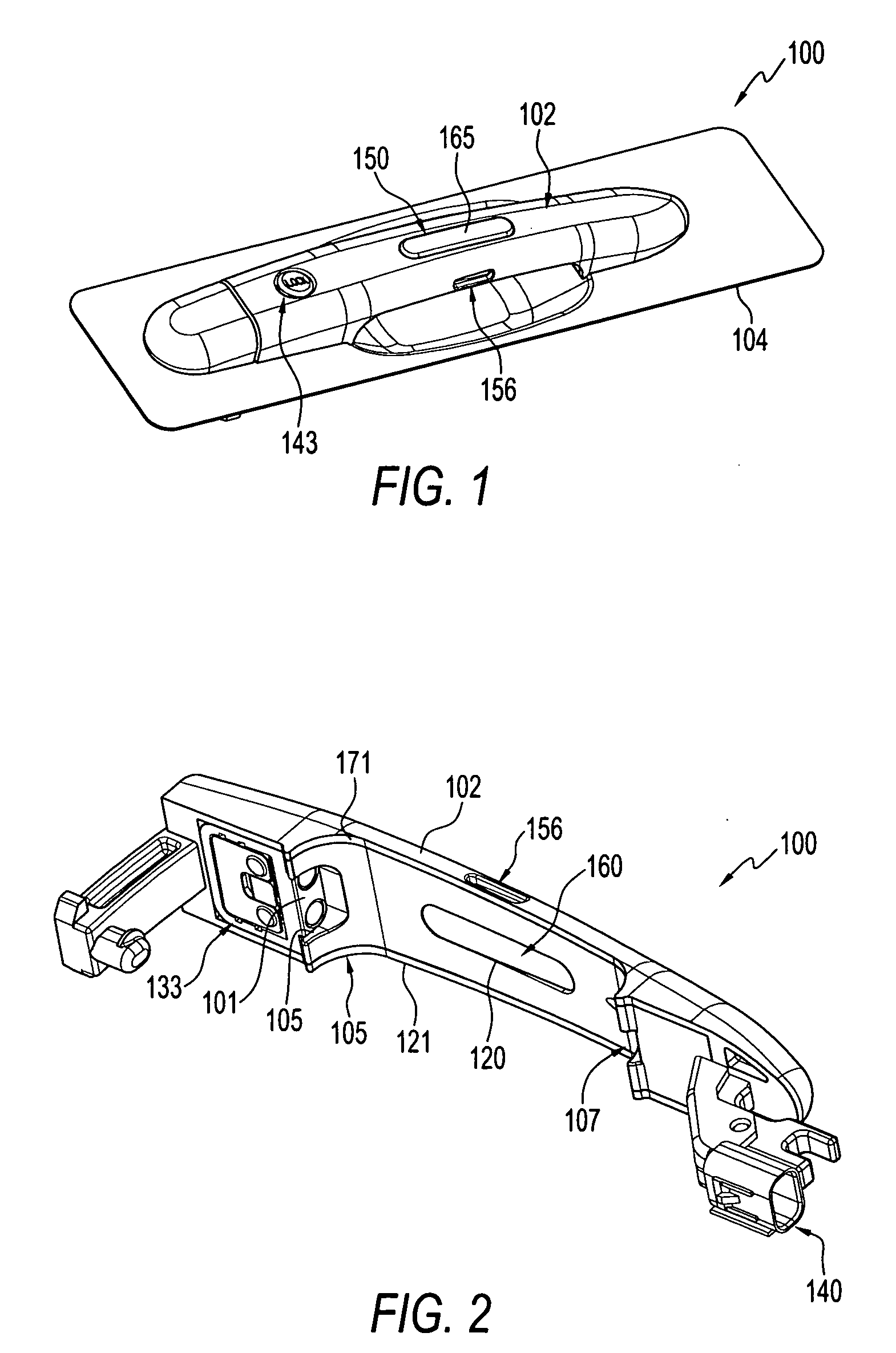
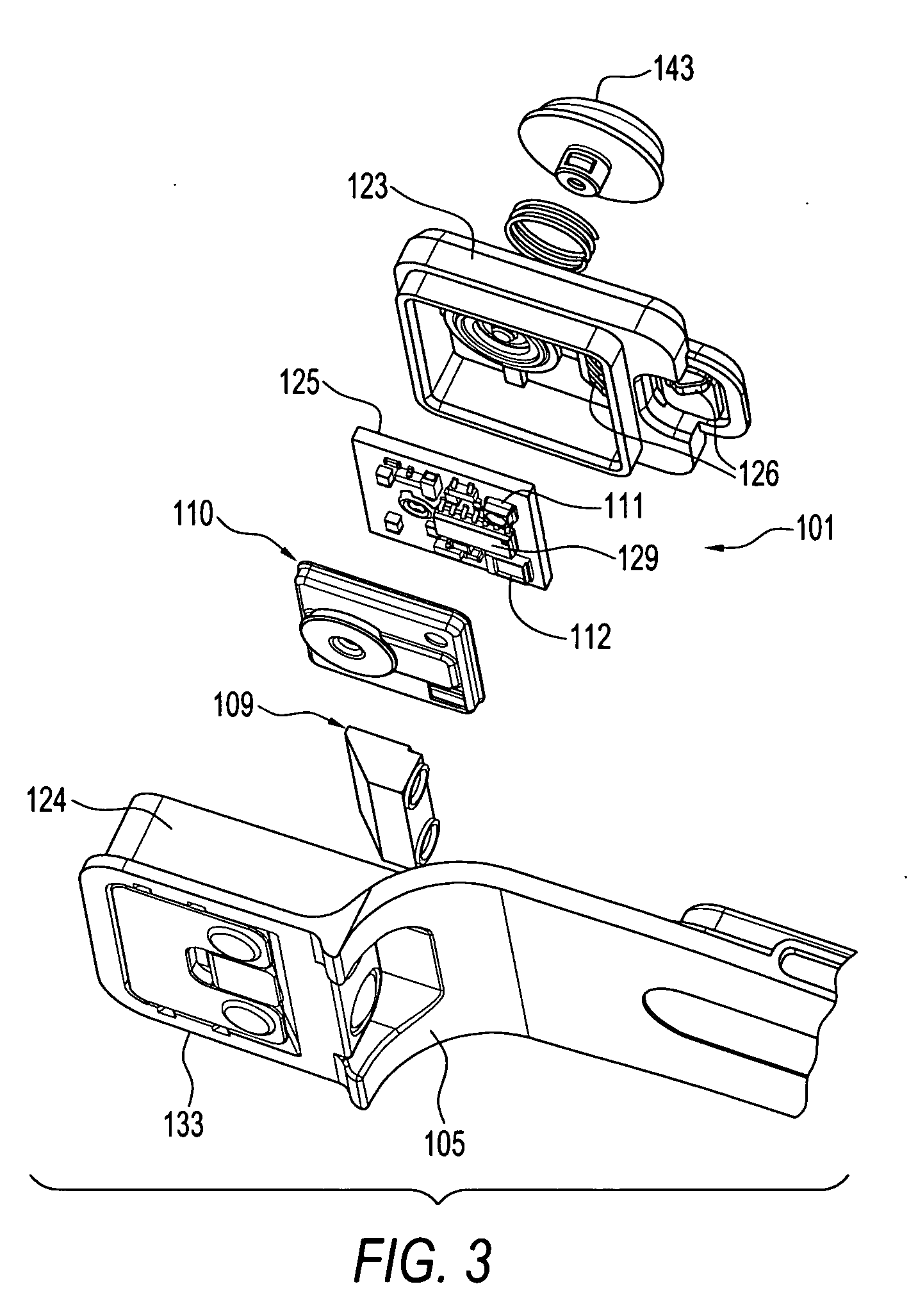
[0052] The method of operating the passive entry system arranged in a door handle of a vehicle will now be described with reference to FIGS. 1, 2, 5 and 6. Initially the vehicle door is locked and as the user begins to approach the vehicle, the control module 52, in response to a signal from an activity sensor, activates the back and ground light LEDs 158, 155, in the handle 102 to illuminate the ground and the door panel beneath the handle. The control module selectively activates the indicator LEDs 152 so that the handle locking button 143 and indicator lens 165 are illuminated red indicating to the user that the door is locked. When the user initially inserts his hand between the handle 102 and the door skin 105 to open the door, the beam is interrupted.

[0053] The signal processor circuitry 58 detects this interruption and interprets this as an authorized user wishing to open the door. The processor transmits a control signal to the control module 52 which then generates an RF s...

second embodiment

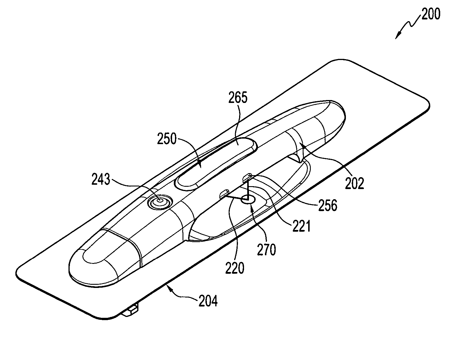
[0055] Reference will now be made to FIGS. 7, 8a and 8b, which illustrate various perspective views of a passive entry sensor system 200 arranged in a door handle according to a As will be described in more detail below, in this embodiment, the optical sensor 201 and indicator module 250 are combined together in a single plug-in unit 271 (shown in broken line in FIG. 8a) arranged about the centre of the handle such that the optical sensor can emit the beam 220 through the rear aperture of the handle 202 at an angle towards the door and detect the beam reflected by the reflector located on the door beneath the handle. The plug-in unit 271 is connected via a wire harness 260 to the connector 240 which connector can be left floating or insert molded into the end of the handle. Combining the indicator module and optical sensor in the plug-in unit 271 facilitates easy and rapid assembly of the sensor and indicator module in the handle without substantial modification of the handle.

[0056...

third embodiment

[0057] Another embodiment of the passive entry system arranged in a door handle assembly is illustrated in exploded view in FIG. 10. In this third embodiment, the optical enclosure of the sensor 301 is mounted in a bracket 370 which is fixed underneath the door skin 304 with the indicator module 350 remaining incorporated into the handle 302. A transparent polycarbonate molding with a front indicator window 365 and rear reflective area is located in a through aperture in the centre of the handle and serves as the optical enclosure of the indicator module.

[0058] The door skin 304 defines an aperture 380 which receives a lens protector assembly 390 through which the emitted beam is transmitted to the reflector (not shown) which is located on the underside of the handle 302. The beam is reflected back from the handle to the sensor. The indicator and back and ground light LEDs are operable by the control module in the same manner as those used in the first and second embodiments. Apertu...


PUM


Abstract

Passive entry sensor systems and associated sensors are disclosed. The system sensor is arranged in the handle of a door or directly mounted to the door skin. When mounted in the handle, the sensor provides an electromagnetic radiation beam transmitted either along the length of the handle between opposite ends thereof or between the handle and the door so that the beam can be at least partially interrupted or modified by a user actuating the handle. When mounted directly to the door skin, the sensor provides an electromagnetic radiation beam transmitted between the handle and the door. The sensor system includes indicators for indicating system status to the user, back-up switches for detecting a pull on the handle, locking switches for activation by a user to lock or unlock the door and backlight and ground light lighting.

Description

CROSS-REFERENCE TO PROVISIONAL PATENT APPLICATION [0001] This patent application claims priority under 35 U.S.C. § 119(e) to provisional patent application Ser. No. 60 / 669,326 entitled “Passive Entry Sensor System,” which was filed on Apr. 7, 2005, the disclosure of which is incorporated herein by reference.TECHNICAL FIELD [0002] Embodiments are generally related to sensing devices and applications. More particularly, embodiments are related to sensor devices and systems for use in keyless access systems which operate passively to enable access by an authorized user to secured environments. Embodiments are additionally related to multi-functional passive entry sensors and systems. Embodiments are also related to passive entry sensors and system configurations utilized in automotive applications. BACKGROUND OF THE INVENTION [0003] It is important, for many reasons, to control access to premises, vehicles and personal property so that only authorized users are allowed access. Typicall...

Claims


Application Information

Patent Timeline
Patent Type & Authority Applications(United States)
IPC IPC(8): G05B19/00
CPCB60R25/00B60R2025/1013E05B81/77G07C2209/65G07C9/00309G07C2009/00793E05B81/78
Inventor SHELLEY, MICHAEL J.CRAWFORD, ALEXSCHWEIZER, PASCALKETTLE, ADRIANGIERCZAK, MAREK
Owner HONEYWELL INT INC
Why Eureka
Try Eureka