Spatial and time multiplexing of multi-band signals

Active Publication Date: 2006-10-12
NOVATEL INC
View PDF11 Cites 70 Cited by
  • Summary
  • Abstract
  • Description
  • Claims
  • Application Information

AI Technical Summary

Benefits of technology

[0013] The disadvantages of prior techniques are overcome by the present invention, which provides a number of improved architectures for use with satellite ranging system receivers. Th

Problems solved by technology

This sampling rate results in d

Method used


Image

  • Spatial and time multiplexing of multi-band signals
  • Spatial and time multiplexing of multi-band signals
  • Spatial and time multiplexing of multi-band signals

Examples


Embodiment Construction

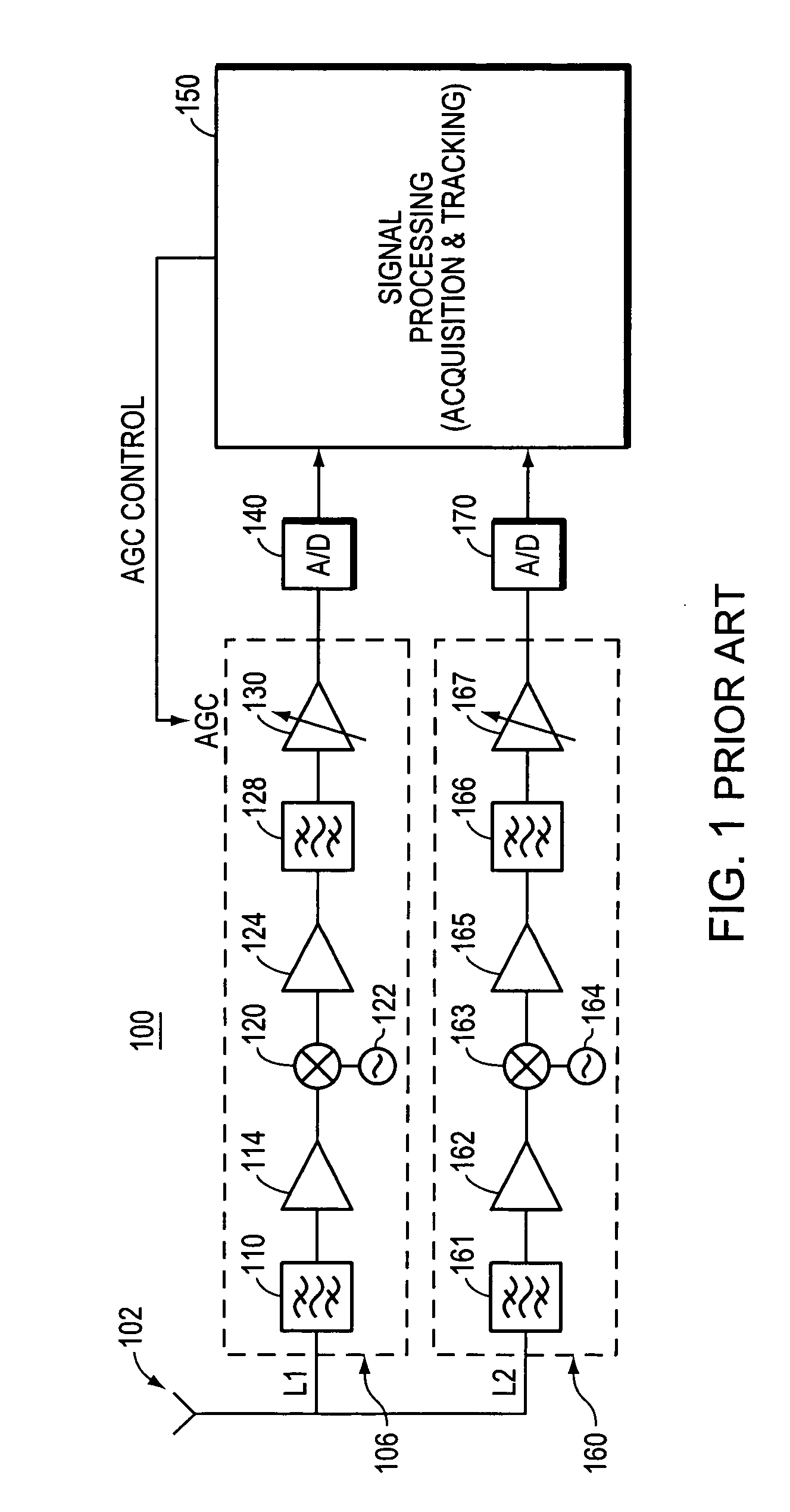
[0034]FIG. 1 is a block diagram of a conventional L1 / L2 heterodyne GPS receiver 100.

[0035] The receiver 100 has an antenna 102 which receives ranging signals in two frequency bands, namely the L1 and L2 bands. The L1 frequency band is associated with the downconverter stage illustrated in the dashed block 106, and is thus referred to herein as the downconverter stage 106. The downconverter stage 106 includes an RF band pass filter 110, which is a low insertion loss filter having a selected pass band centered at a desired carrier frequency. The band pass filter 110 should have a sufficiently wide range to allow several harmonics of the PRN codes to pass. The filtered signal is then passed through a low noise amplifier 114. Thereafter, heterodyning is performed using the mixer 120 which down converts the received signal from the carrier frequency to a desired intermediate frequency by mixing the received signal with a sinusoidal signal of an appropriate frequency that is produced by ...


PUM


Abstract

A multi-band receiver for use with satellite ranging systems is provided. The receiver has a simplified architecture in which input signals of various frequencies are multiplexed together to form a single composite analog signal. In accordance with one embodiment of the invention, this composite signal only requires a single RF circuit for down conversion to an intermediate frequency. The composite, downconverted signal is sampled, and the digitized samples are demultiplexed to form digital counterparts of the original signals from each frequency band. An embodiment for use with elements of a phased array antenna is also provided.

Description

BACKGROUND OF THE INVENTION [0001] 1. Field of the Invention [0002] This invention relates generally to satellite ranging system receivers. [0003] 2. Background Information [0004] There are a number of satellite ranging systems that are currently deployed and additional systems are to be deployed in the near future. Each of these configurations is based upon transmission of ranging signals in particular frequency bands. More specifically, the present United States Global Positioning System (GPS) is based on transmission of ranging signals in two frequency bands known as L1, which is at a center frequency of 1575.42 MHz and L2, centered at 1227.6 MHz. To enhance the reliability and availability of this system, additional GPS signal structures are planned (e.g. L5, L2C). In addition, other satellite ranging systems are being deployed or have been deployed such as that of the Russian Federation, i.e., GLONASS (with two signal structures: G1 and G2), and the European GALL1 LEO system wi...

Claims


Application Information

Patent Timeline
IPC IPC(8): H04L27/08H04L1/02G01S19/24G01S19/36G01S19/53
CPCG01S19/32G01S19/33H04L5/06H04B7/0822H04B7/086G01S19/36
Inventor KUNYSZ, WALDEMARFENTON, PATRICK C.
Owner NOVATEL INC
Why Eureka
Try Eureka