Ultrasound transducer and method of producing the same
- Summary
- Abstract
- Description
- Claims
- Application Information
AI Technical Summary
Benefits of technology
Problems solved by technology
Method used
Image
Examples
Embodiment Construction
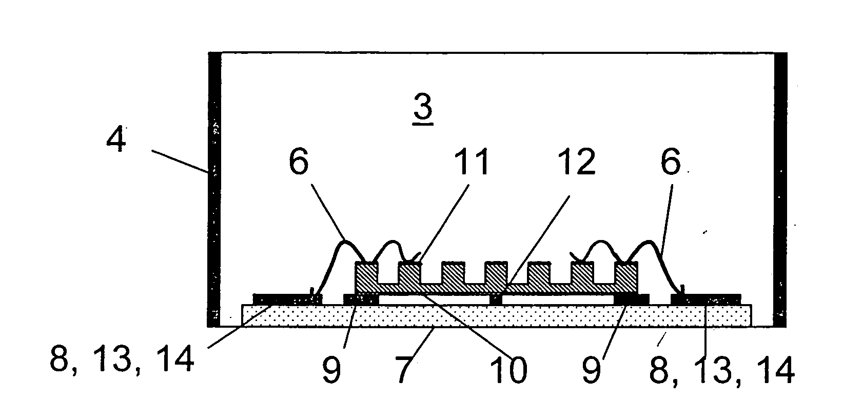
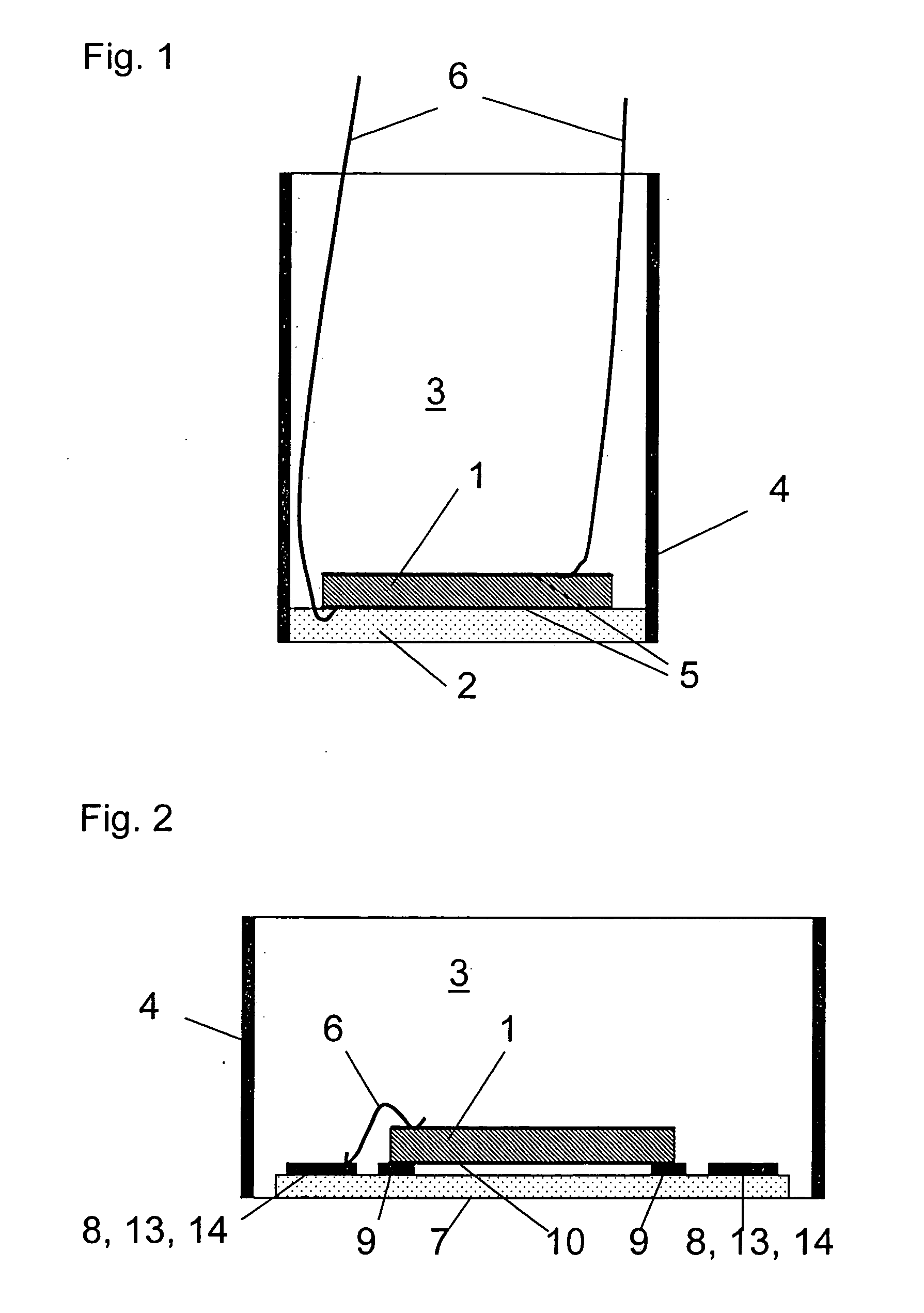
[0033]FIG. 1 shows the basic components of an ultrasound transducer of conventional design which includes a piezoelectric body, the transducer 1, which is firmly connected to the coupling layer 2. The coupling layer 2 has a thickness which is ideally ¼ of the wavelength λ and forms the end wall of a housing 4. Within the housing 4, an attenuation body 3 is disposed which, in the present case, is in the form of a casting material. The two electrodes 5 of the transducer 1 are connected to a control and measuring unit, which is not shown, via electrical cable connectors 6. As mentioned initially, the thickness of the coupling layer is obtained by an expensive mechanical finishing operation.
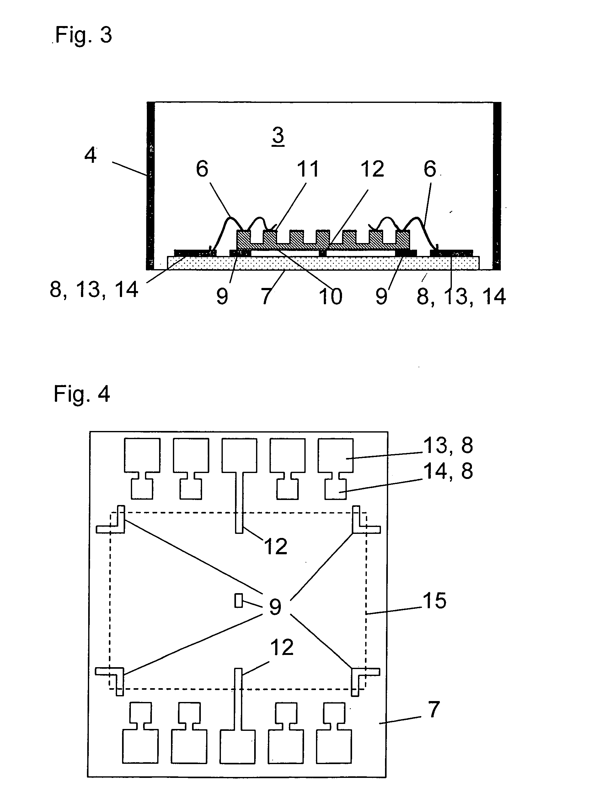
[0034] In order to avoid these problems, an HF plate of the type referred to earlier is used as an adaptation layer and holder for the further working. Onto this plate then a piezoelectric transducer is cemented. The wafer used in connection with the exemplary embodiment is suitable for ultrasound t...
PUM
| Property | Measurement | Unit |
|---|---|---|
| Fraction | aaaaa | aaaaa |
| Electrical resistance | aaaaa | aaaaa |
| Area | aaaaa | aaaaa |
Abstract
Description
Claims
Application Information
 - R&D
- Intellectual Property
- Life Sciences
- Materials
- Tech Scout
- Unparalleled Data Quality
- Higher Quality Content
- 60% Fewer Hallucinations
Browse by: Latest US Patents, China's latest patents, Technical Efficacy Thesaurus, Application Domain, Technology Topic, Popular Technical Reports.
© 2025 PatSnap. All rights reserved.Legal|Privacy policy|Modern Slavery Act Transparency Statement|Sitemap|About US| Contact US: help@patsnap.com


