Valve with bi-loading seal

a valve and sealing technology, applied in the field of valves with bi-loading seals, can solve the problems of increasing the rate of wear, difficult to turn on or off the faucet, and the valve to leak, so as to improve the construction, prolong the life, and improve the sealing

Active Publication Date: 2006-10-19
KOHLER CO
View PDF29 Cites 6 Cited by
  • Summary
  • Abstract
  • Description
  • Claims
  • Application Information

AI Technical Summary

Benefits of technology

[0008] The invention provides a valve having a bi-loading seal with improved construction. The seal resists shearing and failu

Problems solved by technology

Insufficient compressive force can cause the valve to leak at the connection to the fixture.
Too much compressive force can create undesirable resistan

Method used


Image

  • Valve with bi-loading seal
  • Valve with bi-loading seal
  • Valve with bi-loading seal

Examples


Embodiment Construction

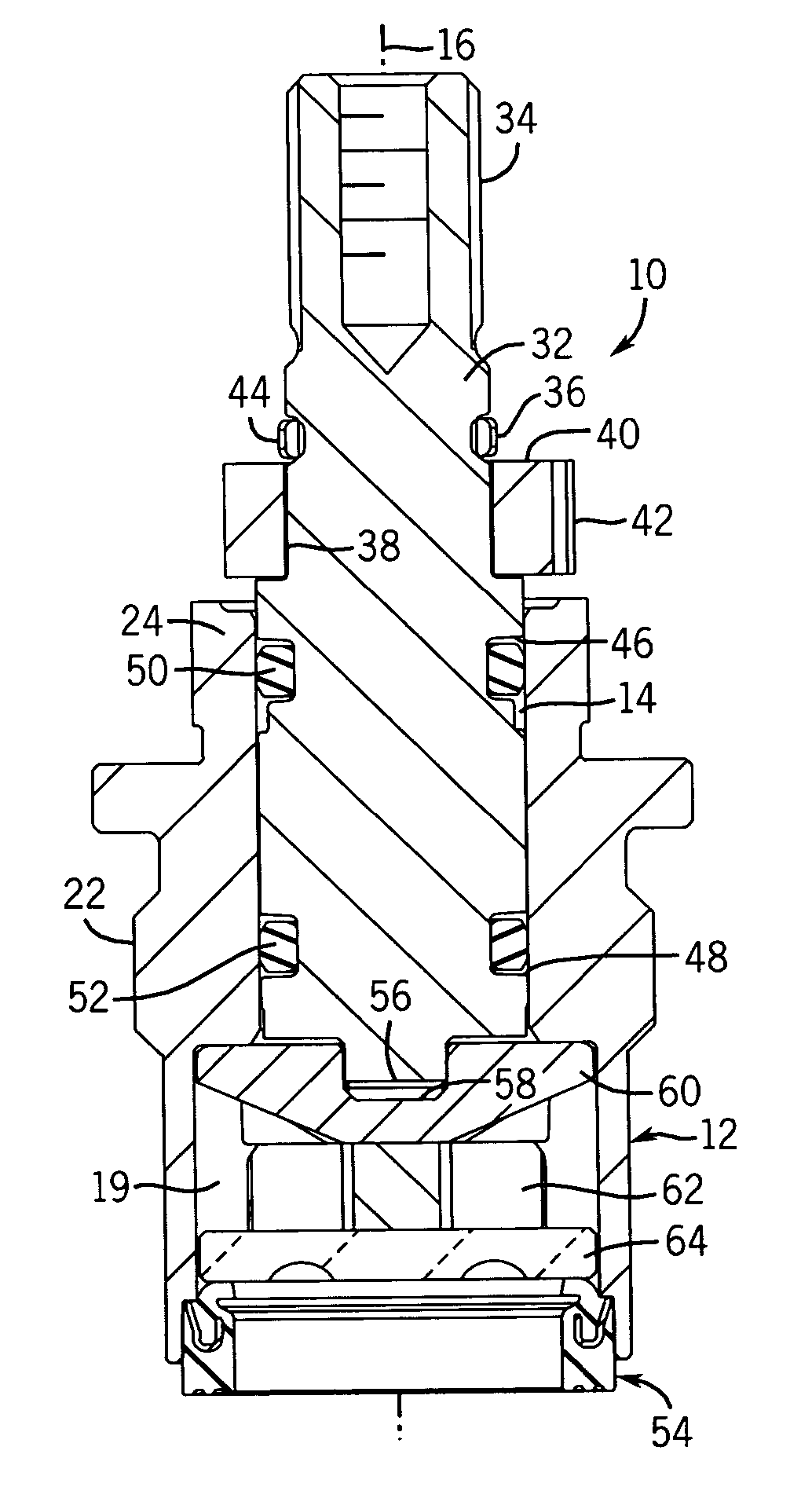
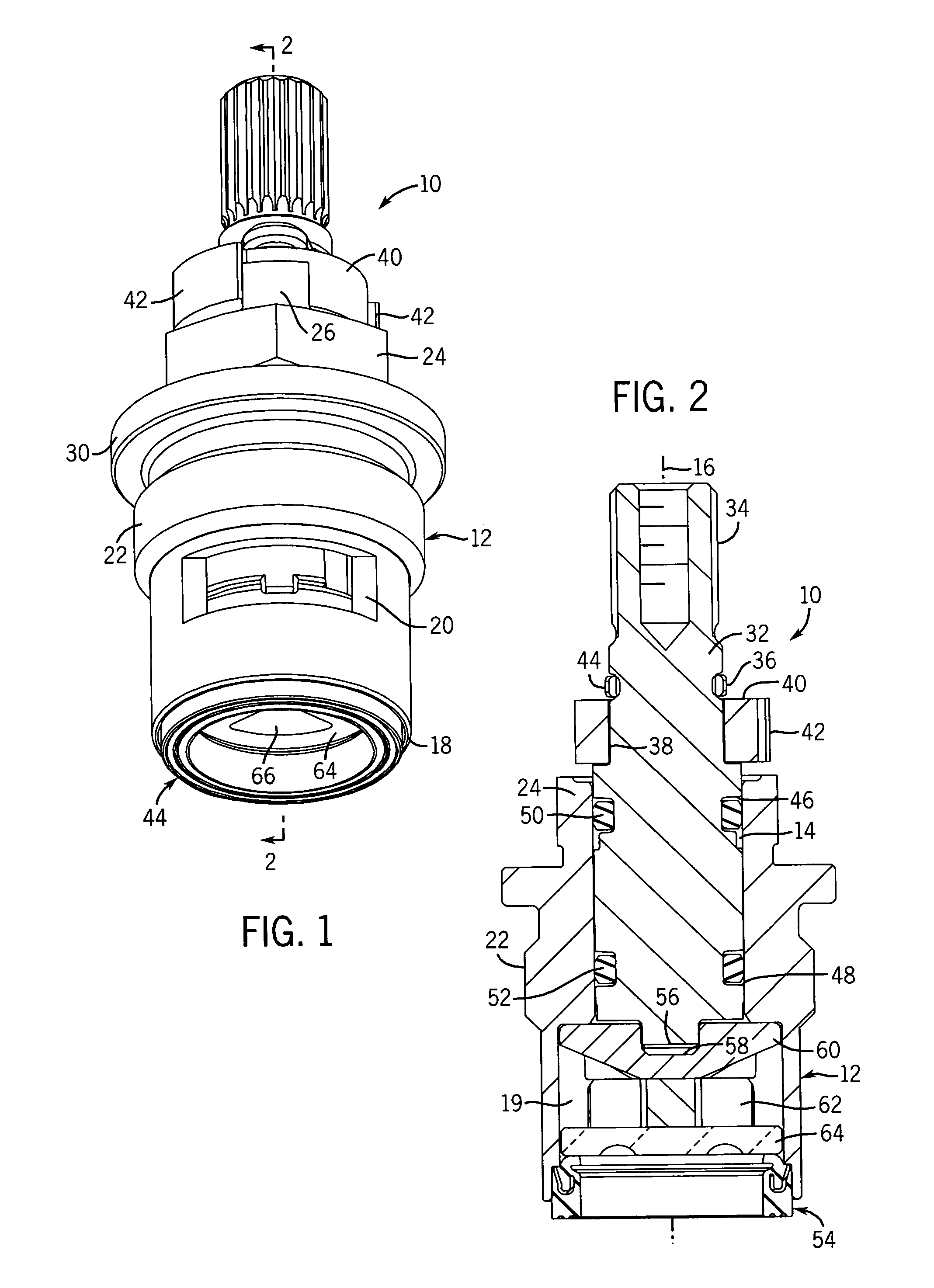
[0021] Referring to FIGS. 1 and 2, the valve cartridge assembly is referred to generally by reference number 10 and includes an annular housing body 12 with an internal cavity 14 disposed along a main axis 16 and in communication with a bottom inlet 18 and two opposite side outlets 20 (one shown). As such, the pathway through the valve is from the inlet 18 up through the a lower portion 19 of the cavity 14 and out through the outlets 20. The housing 12 also defines a threaded section 22 for mating with the fixture (not shown) and a hex section 24 for fastening it in place with a wrench. Two stop tabs 26 (one shown) spaced apart 180 degrees extend upward from the top of the housing. The housing has a larger diameter flange 30 between the threads and the hex section under which sits an o-ring (not shown).

[0022] A spindle / valve stem 32 is disposed along the axis 16 inside the housing 12 and has a splined upper end 34 for mounting a faucet handle (not shown). Below the splined section,...


PUM


Abstract

A fluid control valve has at its lower inlet end a bi-loading seal. The seal is generally ring shaped in top view. However, it has a first flexible load section for sealing the stationary disk with respect to the housing and a second load section having an annular insert that in cross-section is hook-shaped to form a bend of more than 90 degrees. The insert can be molded within the resilient body of the seal so that its outer rim is disposed at a circular shoulder that bears against a seal stop of the housing. A high load can thus be applied between the bearing shoulder and seal stop to achieve a tight seal, while a lower load can be applied between the flexible, unrigidified part of the seal and a stationary valve disk.

Description

CROSS-REFERENCE TO RELATED APPLICATION [0001] Not applicable. STATEMENT OF FEDERALLY SPONSORED RESEARCH OR DEVELOPMENT [0002] Not applicable. BACKGROUND OF THE INVENTION [0003] The invention concerns fluid control valves, such as water control valves used in plumbing fixtures, and seals used therewith. [0004] Valve cartridges and the like are well known for use in faucets and other plumbing fixtures. See e.g., U.S. Pat. No. 5,398,717. Generally, such valves include a cartridge housing with a valve stem that can rotate inside the housing to control a rotatable disk that moves over a stationary disk. The stationary and rotatable disks typically have holes through them that when aligned permit flow, and when completely not aligned shut off flow. These disks are preferably made of ceramic because ceramics are resistant to friction and wear and thus provide for prolonged life of the valve. [0005] Various seals and o-rings are provided between the housing, valve stem, and stationary disk ...

Claims


Application Information

Patent Timeline
IPC IPC(8): F16K27/04
CPCF16K27/045F16K3/08Y10T137/7504Y10T137/7613
Inventor SHAY, CHRISTOPHER M.
Owner KOHLER CO
Why Eureka
Try Eureka