Semiconductor device and manufacturing method thereof
a technology of semiconductor devices and semiconductors, applied in semiconductor devices, load-engaging elements, transistors, etc., can solve the problems of deep formation of the low-voltage mos transistor impurity diffusion layer and degrading the characteristics of the low-voltage mos transistor, and achieves low power consumption, high breakdown voltage, and small structure
- Summary
- Abstract
- Description
- Claims
- Application Information
AI Technical Summary
Benefits of technology
Problems solved by technology
Method used
Image
Examples
embodiment 1
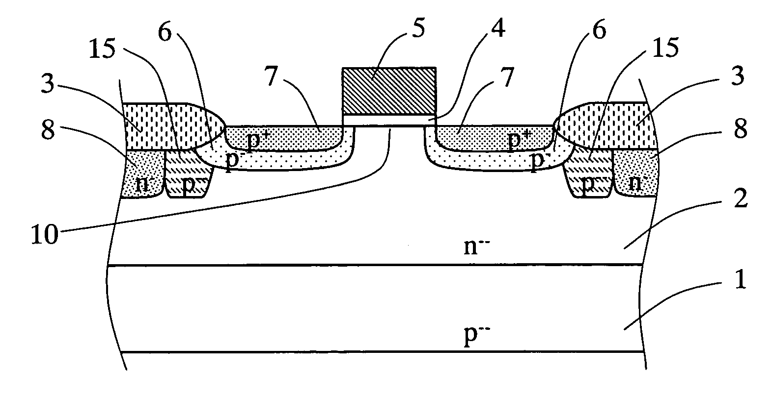
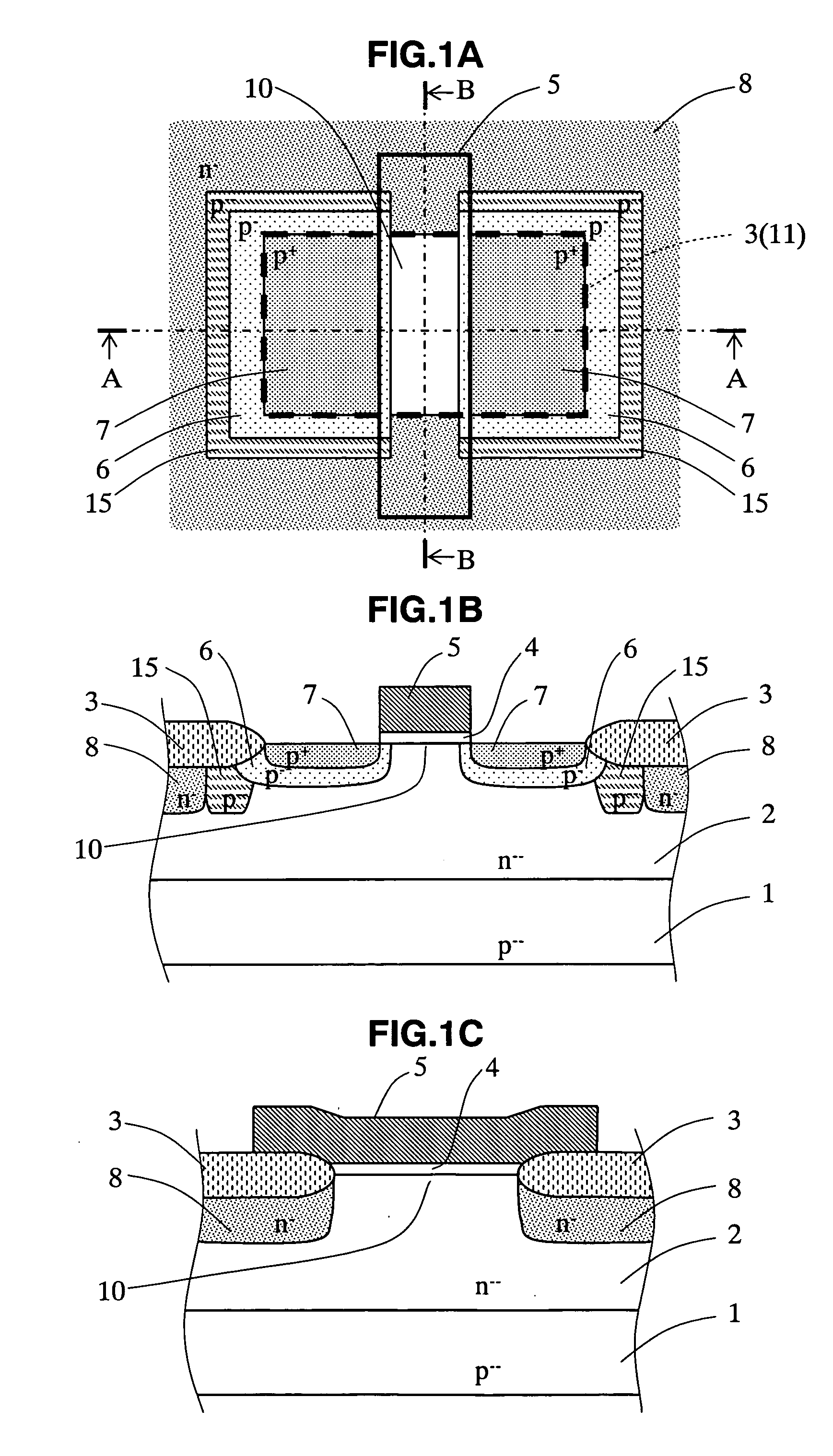
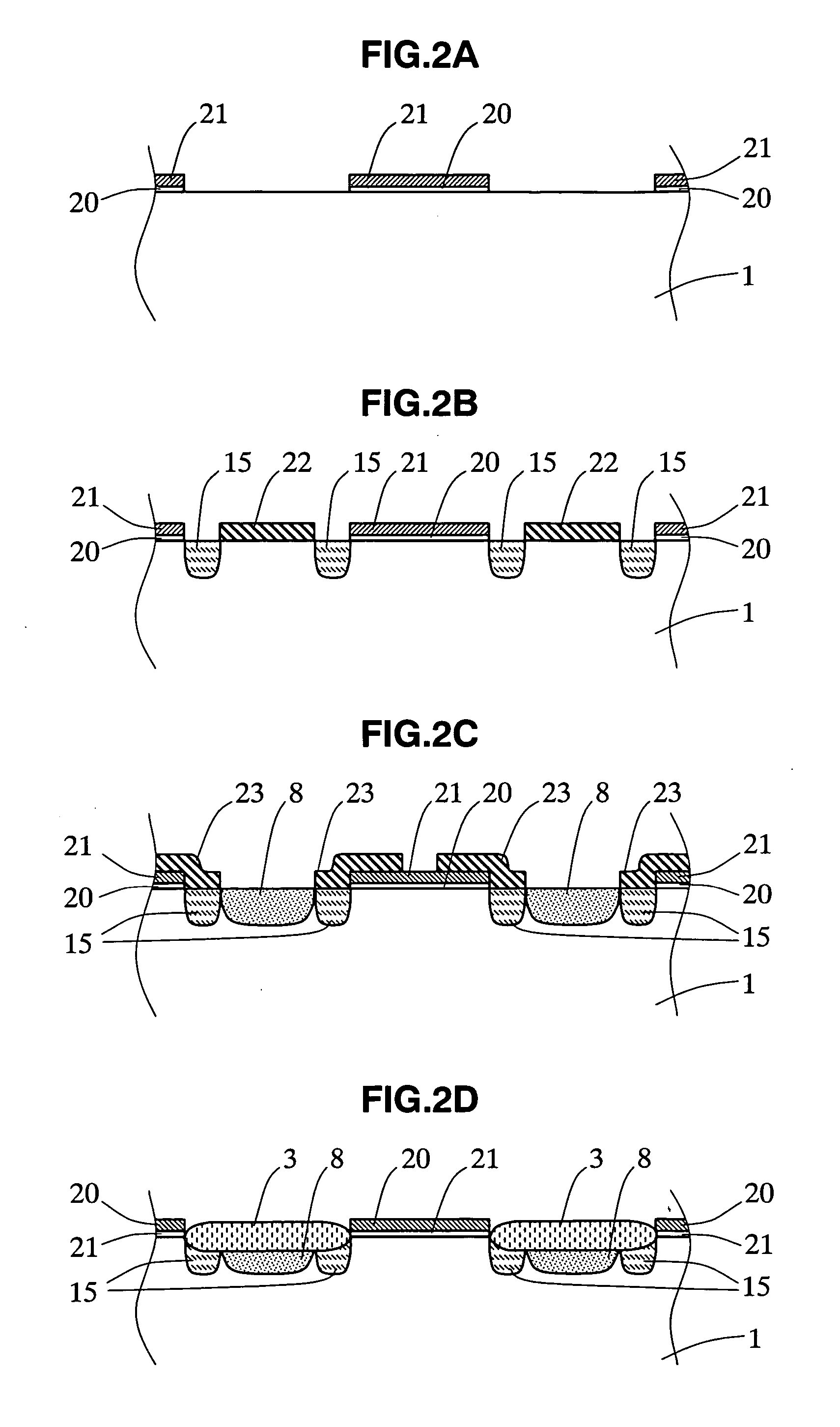
[0047] Below, a semiconductor device of an embodiment 1 of the present invention is explained in detail referring to drawings. FIG. 1A is a plane layout diagram of the semiconductor device of this embodiment, and FIGS. 1B and 1C are cross-sectional views at the A-A line and the B-B line shown in FIG. 1A, respectively. Also, FIGS. 2A to 2D and FIGS. 3A to 3D are process cross-sectional views showing the manufacturing processes of the semiconductor device shown in FIGS. 1A to 1C. In this instance, the process cross-sectional views shown in FIGS. 2A to 2D and FIGS. 3A to 3D correspond to the cross-sections at the A-A line shown in FIG. 1A. Further, FIGS. 4A to 4D are plane views corresponding to FIGS. 2A to 2D, and FIGS. 5A to 5D are plane views corresponding to FIGS. 3A to 3D. Note that in FIGS. 1A to 1C, 2A to 2D, 3A to 3D, 4A to 4D, and 5A to 5C, unlike the conventional semiconductor device explained in FIGS. 11A to 11C, a p-channel MOS transistor is shown as an example. In addition...
embodiment 2
[0083] Next, a semiconductor device of an embodiment 2 of the present invention is explained in detail hereafter, with reference to the drawings. FIG. 10A is a plane layout diagram of the semiconductor device of this embodiment, and FIGS. 10B and C are cross-sectional views at the C-C line and the B-B line in FIG. 10A. The A-A cross-section in FIG. 10A is the same as the cross-sectional view shown in FIG. 1B. Also, FIGS. 10A to 10C illustrate a p-channel MOS transistor in the same way as in FIGS. 1A to 1C.
[0084] As shown in FIGS. 10A and 10C, the semiconductor device of this embodiment is different from the first embodiment in that in the region immediately below the gate electrode 5, the channel region 10 between the source region and the drain region projects along the gate electrode 5 toward the channel stopper region 8 (the channel stopper region 8 is retreated) and the channel region 10 is formed contacting the channel stopper region 8, and that the non-formation region 11 (a ...
PUM
 Abstract
Description
Claims
Application Information
 - R&D
- Intellectual Property
- Life Sciences
- Materials
- Tech Scout
- Unparalleled Data Quality
- Higher Quality Content
- 60% Fewer Hallucinations
Browse by: Latest US Patents, China's latest patents, Technical Efficacy Thesaurus, Application Domain, Technology Topic, Popular Technical Reports.
© 2025 PatSnap. All rights reserved.Legal|Privacy policy|Modern Slavery Act Transparency Statement|Sitemap|About US| Contact US: help@patsnap.com


