
Method and device for determining the resonant frequency of resonant piezoelectric sensors

a piezoelectric sensor and resonant frequency technology, applied in measurement devices, material analysis using sonic/ultrasonic/infrasonic waves, instruments, etc., can solve the problems of large inaccuracy and performance degradation, time-consuming and error-prone, and restrict the operating range of the sensor, etc., to achieve convenient use, low cost, and compact

Inactive Publication Date: 2006-10-19
TECHNOBIOCHIP S C A R L
View PDF5 Cites 14 Cited by
  • Summary
  • Abstract
  • Description
  • Claims
  • Application Information

AI Technical Summary

Benefits of technology

[0016] The task of the present invention is to propose a method and a device that offer the typical advantages provided by the oscillators in terms of compactness, ease of use for unspecialized personnel, and low cost, while, at the same time, overcoming the limitations of the systems known to date.
[0018] Another object of the present invention is to propose a method of the above cited type which enables to take extremely accurate measurements even in the cases where the resonant sensor is subject to high damping.
[0020] Still another object of the present invention is to indicate a device which is low-cost and easy to implement and use as to determine in a fully automated way the value of the resonant frequency of a resonant sensor subject to an acousto-mechanical and / or dielectric loads
[0024] The oscillator circuit of the device according to the present invention proposes and implements a technique to obtain an active and automatic compensation of the sensor parallel capacitance, and to maintain the oscillation frequency of the circuit constantly equal to the frequency where the phase of the sensor impedance is null. Under the condition of neutralization of the parallel capacitance, such a frequency exactly corresponds to the sensor resonant frequency, irrespective of the degree of damping. Moreover, the circuit automatically follows the above frequency, thereby providing an accurate and reliable measurement of the sensor response.

Problems solved by technology

However, when the sensor is subject to heavy acoustic and / or dielectric loads, such for measurements in contact with liquids or with viscoelastic media, the sensor resonant frequency and the output frequency of the oscillator circuit can become significantly different, thereby resulting in large inaccuracies and performance degradation.
As a limiting case, under high damping, the oscillator may stop operating properly and cease to sustain oscillations, therefore restricting the sensor operating range.
However, in such known oscillator circuits the compensation implies a manual adjustment which is time consuming and error prone.
Moreover, such known oscillator circuits do not allow to measure the value of the compensated capacitance, which, on the contrary, can be of significant interest in several applications.
This approach, though provides satisfying results, brings about some limitations.
In fact, the particular configuration adopted to simulate the negative capacitance in some of the above referenced studies can become unstable under certain circumstances; moreover, in none of the circuits of the above referenced studies the sensor has one terminal connected to ground, which instead would be desirable in several electrochemical and biological applications.
7—July 2002) introducing a circuit which, however, requires a number of lengthy calibration operations to be performed with the unperturbed sensor.
A solution is also mentioned which would enable the automation of the calibration steps of the system and the parallel capacitance compensation, but this would make the circuit even more complex and costly.
They, however, are costly instruments, require specialized personnel to operate them, and, as such, are essentially limited to laboratory use.

Method used


Image

  • Method and device for determining the resonant frequency of resonant piezoelectric sensors
  • Method and device for determining the resonant frequency of resonant piezoelectric sensors
  • Method and device for determining the resonant frequency of resonant piezoelectric sensors

Examples


Embodiment Construction

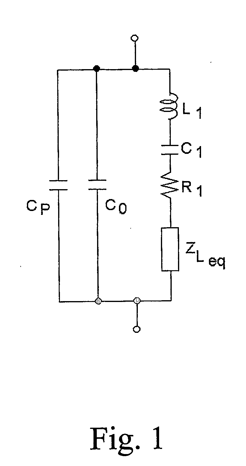
[0032] A quartz crystal resonant sensor subject to both acousto-mechanical and dielectric loading can be represented around its fundamental resonant frequency by the equivalent circuit of FIG. 1 (extended BVD model).

[0033] In the circuit, the components L1, C1 and R1 form the mechanical (i.e. motional) branch of the model and represent the equivalents of mass, elastic compliance, and mechanical losses, respectively, of the unloaded sensor. The capacitor C0 represents the dielectric behavior of the sensor associated to the crystal capacitance.

[0034] The acousto-mechanical load is represented by the equivalent impedance ZLeq, while CP is the additional capacitance arising from contact with, or immersion into, a liquid whose conductivity is assumed to be negligible.

[0035] More specifically, ZLeq can be purely inductive in the case of simple mass accumulation, or complex when an appreciable damping is also present, such as for instance in case of dense and viscous liquids or with vis...


PUM


Abstract

A method and a device are disclosed to determine the value of the resonant frequency of a resonant sensor subject to an acoustomechanical and / or dielectric load. The sensor is simultaneously and constantly excited at two different frequencies, the first of which is the series resonant frequency, while the second is introduced to detect and compensate the sensor parallel capacitance in an automatic and continuous way.

Description

FIELD OF THE INVENTION [0001] The present invention relates to a method and a device for determining the resonant frequency of piezoelectric resonant sensors subject to a load. BACKGROUND OF THE INVENTION [0002] Piezoelectric resonant sensors based on AT-cut quartz crystals vibrating in thickness-shear mode (TSM) are used as quartz-crystal microbalances (QCM), film-thickness monitors, sensors for physical-chemical properties of fluids, and as transduction devices for chemical and biochemical sensors. [0003] Quartz crystal resonant sensors are widely used in the chemical, medical, biotechnology, environmental, food, materials, and process control fields. [0004] The primary output signal of this kind of sensors is the crystal resonant frequency, which needs to be accurately determined since it directly relates to the quantity to be measured. [0005] To this purpose, oscillator circuits are typically used in which the crystal is inserted as the frequency-controlling element. However, wh...

Claims


Application Information

Patent Timeline
IPC IPC(8): G01R27/28G01N27/00
CPCG01N2291/0256G01N29/036
Inventor VITTORIO, FERRARIDANIELE, MARIOLIANDREA, TARONI
Owner TECHNOBIOCHIP S C A R L
Learn More