Inductor unit and oscillator using the inductor unit

a technology of inductors and inductors, which is applied in the direction of oscillator, electrical apparatus, etc., can solve the problems of increasing the bandwidth of voltage-controlled oscillator, not affording sufficient fine tuning of oscillation frequency, and inductors built into the ic device, etc., to achieve stable oscillation characteristics, increase inductance, and increase q

Inactive Publication Date: 2006-10-19
PANASONIC CORP
View PDF3 Cites 24 Cited by
  • Summary
  • Abstract
  • Description
  • Claims
  • Application Information

AI Technical Summary

Benefits of technology

[0019] Furthermore, by the nonlinearity of the variable capacitance device and the temperature characteristic of the variable capacitance device and fixed capacitors can be corrected to the ideal characteristic. Because the conversion gain Kv of the voltage-controlled oscillator is constant regardless of capacitance control signal, the lockup time and C/N characteristic of the PLL incorporating the voltage-controlled oscillator are constant to the oscillation frequency, and a stable oscillation characteristic can be achieved.
[0020] The inductor unit of the pres

Problems solved by technology

This arrangement increases the bandwidth of the voltage-controlled oscillator but does not afford sufficiently fine tuning the oscillation frequency because correcting for variation in the inductors built in to

Method used


Image

  • Inductor unit and oscillator using the inductor unit
  • Inductor unit and oscillator using the inductor unit
  • Inductor unit and oscillator using the inductor unit

Examples


first embodiment

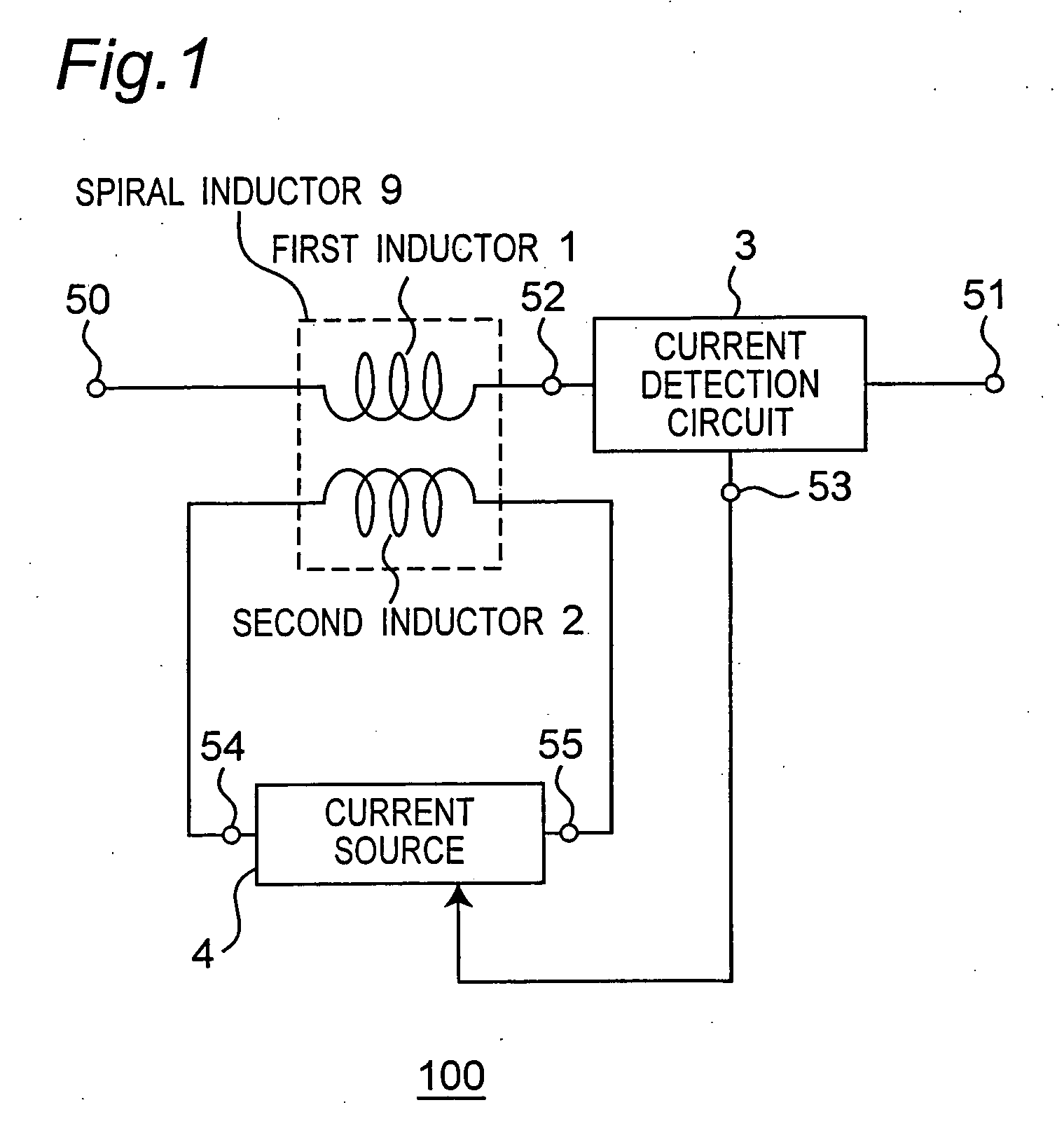
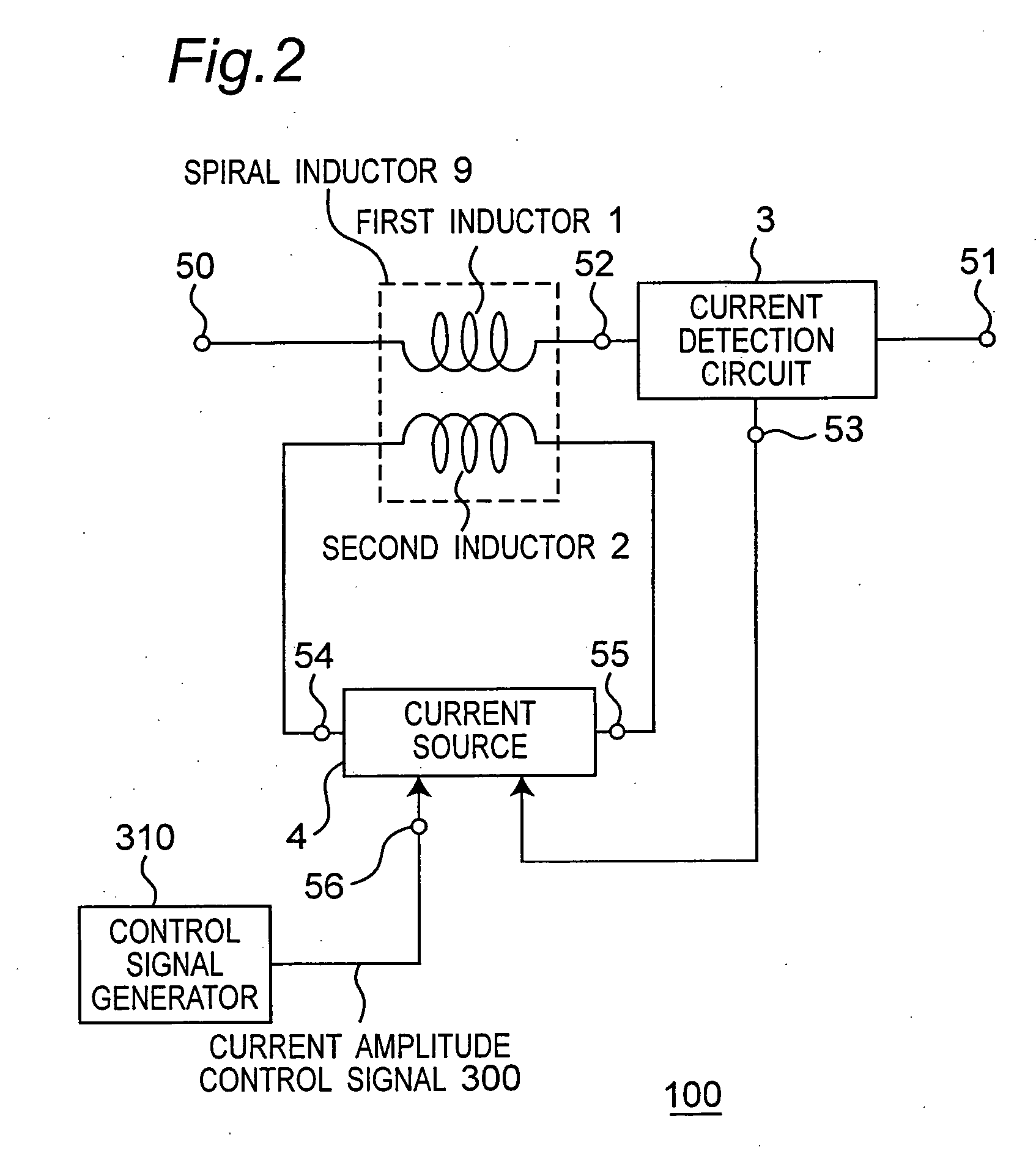
[0069]FIG. 1 is a block diagram of an inductor unit according to a first embodiment of the invention.

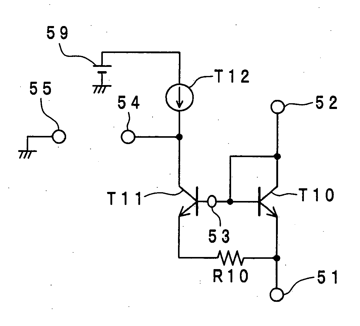
[0070] One end of the first inductor 1 is connected to a current detection circuit 3 through node 52, and the other end of the first inductor 1 is connected to node 50. The current detection circuit 3 is connected to node 51 and node 53 in addition to node 52. The current source 4 is connected to the current detection circuit 3 through node 53, and is connected through node 54 and node 55 to one side and the other side, respectively, of the second inductor 2. The circuitry between node 50 and node 51 is inductor unit 100.

[0071] The current flowing to the first inductor 1 also flows between node 51 and node 52 through the current detection circuit 3, and the frequency, phase, and current amplitude of the current are detected by the current detection circuit 3. The current source 4 generates a current signal of the same frequency, same phase, and current amplitude of a predetermined ...

second embodiment

[0117] The second embodiment of the invention described below is a voltage-controlled oscillator.

[0118]FIG. 9 is a block diagram of a voltage-controlled oscillator 110 according to this second embodiment of the invention.

[0119] As shown in FIG. 9, the voltage-controlled oscillator 110 comprises a differential oscillation unit 80 having transistors 7A and 7B, a variable capacitor unit 81 that uses varactor diodes 6A and 6B as variable capacitance elements, and a variable inductor unit 82 having spiral inductors 9A and 9B. The differential oscillation unit 80 oscillates using the inductance-capacitance parallel resonance circuit comprising variable inductor unit 82 and variable capacitor unit 81 as the load.

[0120] In the differential oscillation unit 80 the transistors 7A and 7B are connected with the base of one connected to the collector of the other, and the output signals Pout1 and Pout2 of the voltage-controlled oscillator 110 output from these two nodes. The emitters of trans...


PUM


Abstract

Functionality and performance of a voltage-controlled oscillator are improved by continuously controlling inductor output by a control signal. Having a first inductor, a current detection circuit that detects current flow to the first inductor, a current source 4 for generating a current signal based on the detected current, and a second inductor to which the current signal is applied, the first inductor and second inductor are disposed to a predetermined magnetically coupled position for setting the inductance of the first inductor as desired.

Description

BACKGROUND OF THE INVENTION [0001] 1. Field of Technology [0002] The present invention relates to technology for a voltage-controlled oscillator that is used in wireless communication devices having a portable terminal. [0003] 2. Description of Related Art [0004] A voltage-controlled oscillator (VCO) is used in portable wireless devices such as cell phones for frequency conversion operations converting transmission signals to high frequency signals for transmission and converting reception signals to low frequency signals for demodulation. These applications require a wide oscillation frequency range, the ability to freely adjust the oscillation frequency, and a high carrier-to-noise (C / N) ratio in the oscillation frequency. [0005] Semiconductor devices used in the communications industry today often have an internal voltage-controlled oscillator. Spiral inductors are generally used when the inductor is also built in to the IC device. A wide oscillation frequency band is achieved in...

Claims


Application Information

Patent Timeline
IPC IPC(8): H03B5/08
CPCH03B5/1231H03B5/1215H03B5/1271H03B5/1265H03B5/1243
Inventor HINO, TAKUO
Owner PANASONIC CORP
Why Eureka
Try Eureka