Hearing aid

a technology of hearing aids and microphones, applied in the direction of behind the ear hearing aids, piezoelectric/electrostrictive transducers, transducer types, etc., can solve the problems of complex mechanical design, high humidity sensitivity of conventional microphones, device failure, etc., and achieve the effect of easy evaluation

Inactive Publication Date: 2006-10-19
SIVANTOS PTE LTD
View PDF1 Cites 87 Cited by
  • Summary
  • Abstract
  • Description
  • Claims
  • Application Information

AI Technical Summary

Benefits of technology

[0017] With a further embodiment, provision is made for the membranes of the number of microphones to each comprise d

Problems solved by technology

Furthermore, conventional microphones exhibit a high sensitivity towards humidity.
An excessively high air humidity frequently

Method used


Image

  • Hearing aid
  • Hearing aid

Examples


Embodiment Construction

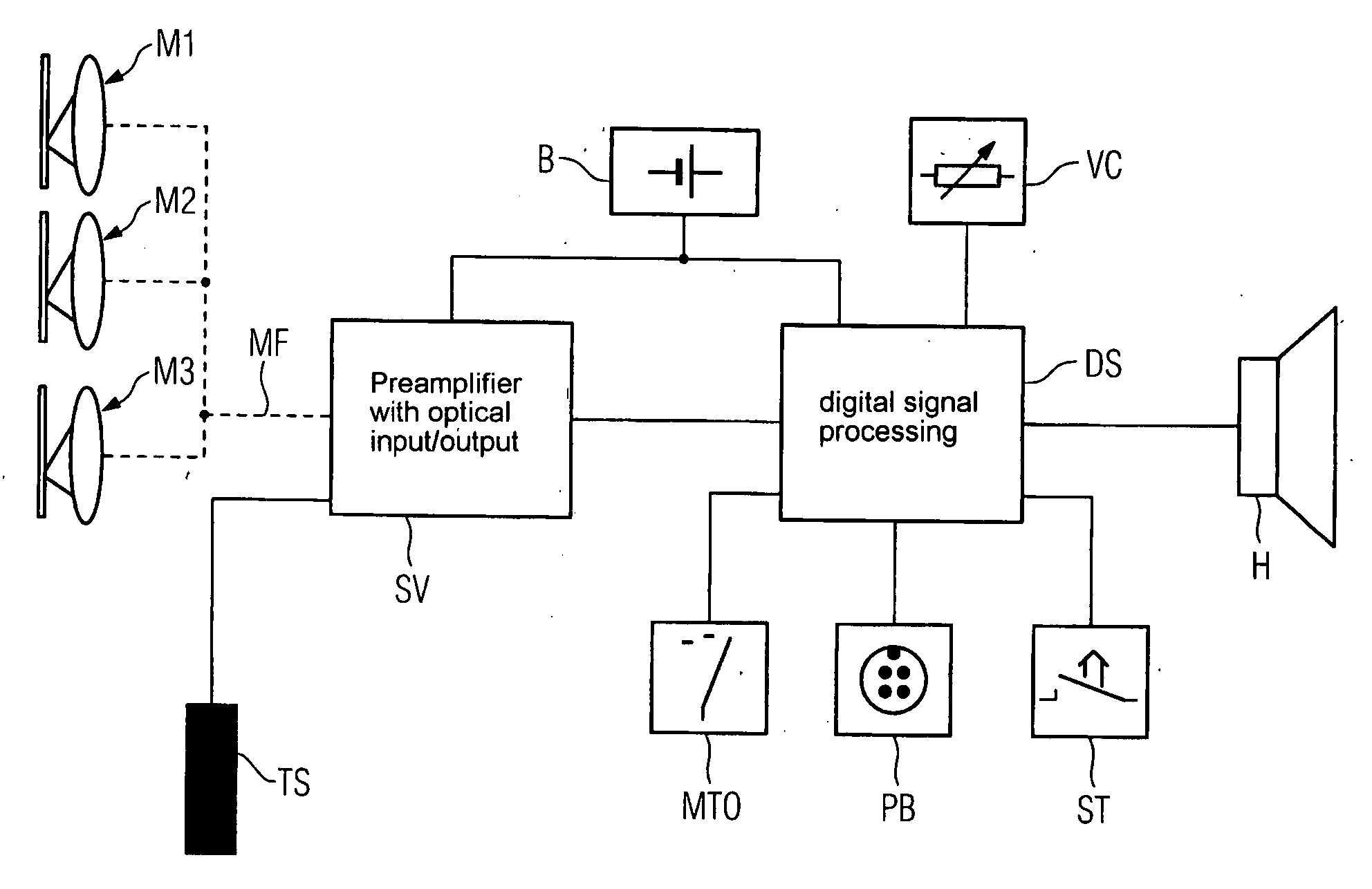
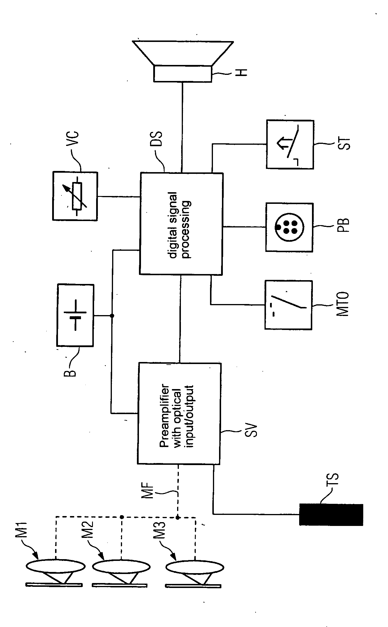
[0020] The hearing aid device selected in the exemplary embodiment features three optical microphones M1, M2 and M3. A membrane is scanned in each optical microphone using suitable optics, said membrane being moved through the incoming sound. The microphones M1, M2 and M3 form a so-called microphone array, with the functionality of a directional microphone being able to be ensured for instance. Hearing aid devices with two, four, five etc. optical microphones can naturally also be realized.

[0021] The individual microphones M1, M2 and M3 are supplied with the light of a laser diode via a common multimode fiber MF, which is correspondingly branched, said laser diode being arranged in the control and preprocessing unit SV. Aside from the optical output, this control and preprocessing unit SV also contains a preamplifier with an optical input, so that the optical signals incoming from the individual microphones M1, M2 and M3 via the multimode fiber MF can be preamplified.

[0022] Altern...


PUM


Abstract

The robustness of hearing aid devices in terms of electromagnetic disturbances and chemically aggressive surroundings should be improved. For this purpose, provision is made to equip a hearing aid apparatus with optical microphones. Since no metal parts must be used for these optical micro-phones, corrosion can be largely excluded. Furthermore, no EMC problems occur as a result of the optical signal processing.

Description

CROSS REFERENCE TO RELATED APPLICATIONS [0001] This application claims priority to the German Application No. 10 2005 013 833.0, filed Mar. 24, 2005 which is incorporated by reference herein in its entirety. FIELD OF INVENTION [0002] The present invention relates to a hearing aid apparatus with at least one microphone. Aside from the conventional behind-the-ear hearing devices and in-the-ear hearing devices, the present invention particularly also relates to implants. BACKGROUND OF INVENTION [0003] Hearing aid devices feature one or a number of microphones. Electret microphones are typically used in the hearing aid devices. These and / or their downstream signal processing, if applicable, nevertheless indicate problems regarding the electromagnetic compatibility (EMC). This is due, on the one hand, to the microphone conductors operating as antennae and the impedance converters in the microphone operating as demodulators. The electromagnetic waves, which are injected across the microph...

Claims


Application Information

Patent Timeline
IPC IPC(8): H04R25/00
CPCH04R23/008H04R2225/021H04R2225/023H04R2225/025H04R2225/67
Inventor HUSUNG, KUNIBERT
Owner SIVANTOS PTE LTD
Why Eureka
Try Eureka