RF transmission error detection and correction module

a technology of transmission error detection and correction module, which is applied in the field of wireless communication systems, can solve problems such as insufficient static calibration of rf signals, adversely and affecting the signal integrity of rf signals

Inactive Publication Date: 2006-10-19
AVAGO TECH INT SALES PTE LTD
View PDF6 Cites 15 Cited by
  • Summary
  • Abstract
  • Description
  • Claims
  • Application Information

AI Technical Summary

Problems solved by technology

As is known, an imbalance (e.g., magnitude difference and / or phase offset) between the in-phase and quadrature components of the baseband signal adversely affects signal integrity of the RF signal.
Another issue that affects the signal integrity of RF signals is mismatches in the mixers that produce what is generally referred to a local oscillation leakage (LO leakage).
However, such static calibrations may not adequately compensate for dynamic changes within the transmitter during an RF transmission.

Method used


Image

  • RF transmission error detection and correction module
  • RF transmission error detection and correction module
  • RF transmission error detection and correction module

Examples


Embodiment Construction

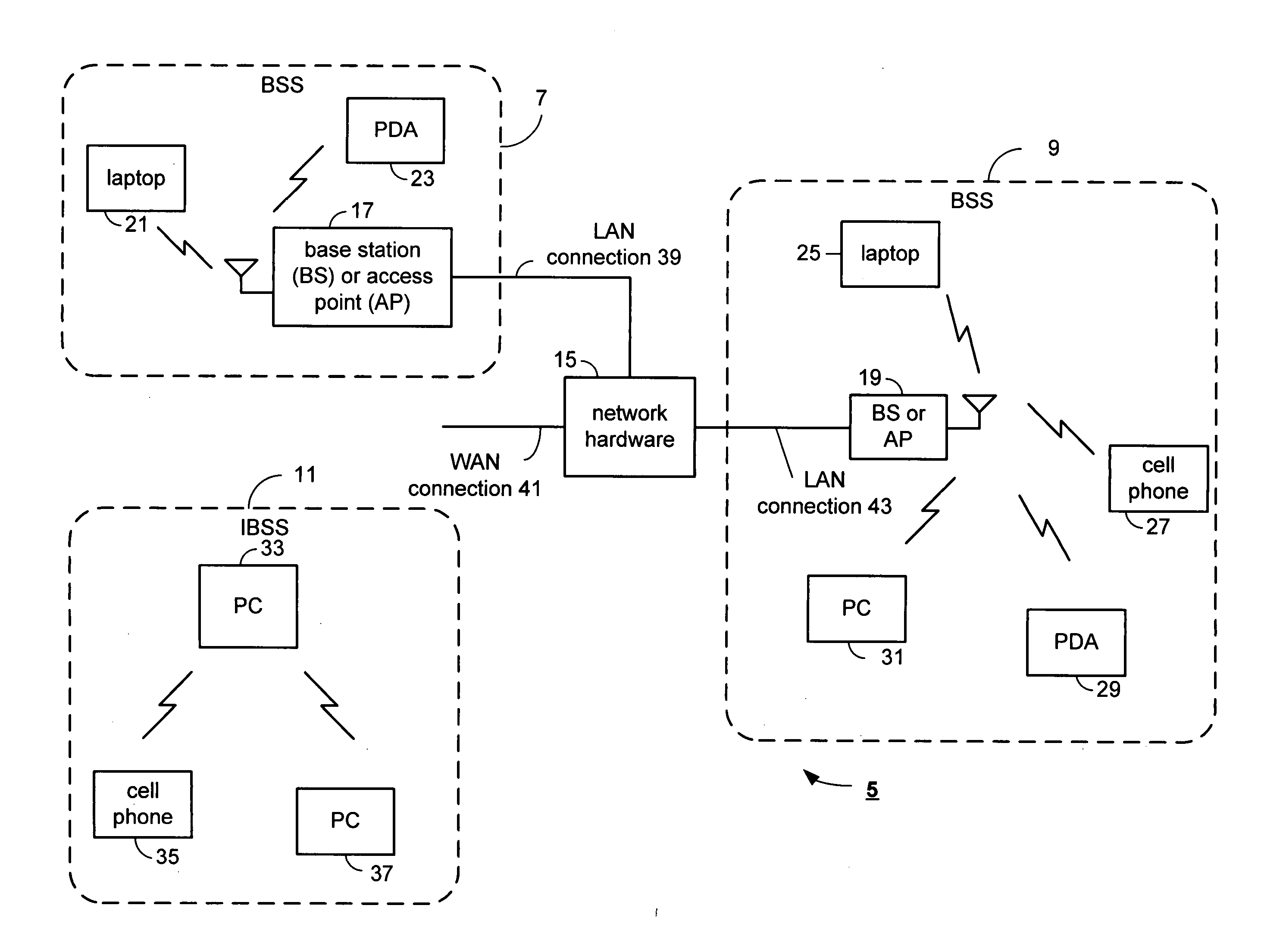
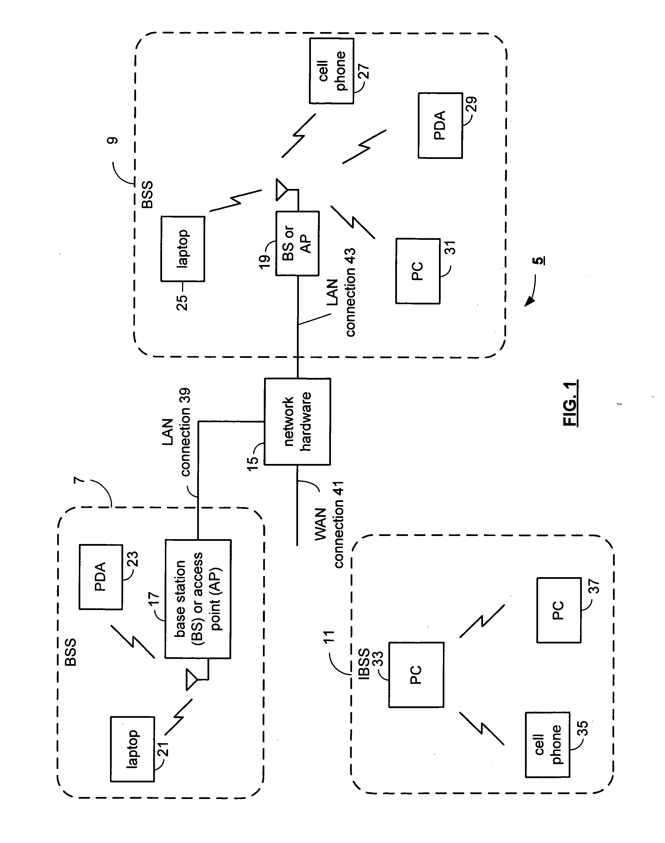
[0020]FIG. 1 illustrates a schematic block diagram of a communication system 5 that includes basic service set (BSS) areas 7 and 9, an independent basic service set (IBSS) 11, and a network hardware device 15. Each of the BSS areas 7 and 9 include a base station and / or access point 17, 19 and a plurality of wireless communication devices 21-23, 25-31. The IBSS 11 includes a plurality of wireless communication devices 33-37. Each of the wireless communication devices 21-37 may be laptop host computers 21 and 25, personal digital assistant hosts 23 and 29, personal computer hosts 31 and 33 and / or cellular telephone hosts 27 and 35.

[0021] The base stations or access points 17 and 19 are operably coupled to the network hardware 15 via local area network connections 39 and 43. The network hardware 15, which may be a router, switch, bridge, modem, system controller, et cetera provides a wide area network connection 41 for the communication system 5. Each of the base stations or access po...


PUM


Abstract

A radio frequency (RF) transmission correction module includes an RF transmission error detection module and a correction module. The error detection module includes an RF envelope detector, a signal conversion module, and an error detection module. The RF envelope detector is operably coupled to produce an envelope signal from a transmit RF signal, wherein the envelope signal represents at least one of local oscillation leakage and in-phase (I) and quadrature (Q) imbalance. The signal conversion module is operably coupled to convert the envelope signal into an error signal in accordance with baseband processing of the transmit RF signal. The error detection module is operably coupled to determine at least one of a local oscillation leakage value and an I and Q imbalance value from the error signal. The correction module is operably coupled to produce at least one of a local oscillation leakage correction signal and an I and Q imbalance correction signal based on the at least one of the local oscillation leakage value and the I and Q imbalance value, respectively.

Description

CROSS REFERENCE TO RELATED PATENTS [0001] This invention is claiming priority under 35 USC § 119(e) to a provisionally filed patent application having the same title as the present patent application, a filing date of Mar. 29, 2005 and an application number of 60 / 666,212.BACKGROUND OF THE INVENTION [0002] 1. Technical Field of the Invention [0003] This invention relates generally to wireless communication systems and more particularly to radio frequency (RF) transmission error detection and correction. [0004] 2. Description of Related Art [0005] Communication systems are known to support wireless and wire lined communications between wireless and / or wire lined communication devices. Such communication systems range from national and / or international cellular telephone systems to the Internet to point-to-point in-home wireless networks. Each type of communication system is constructed, and hence operates, in accordance with one or more communication standards. For instance, wireless ...

Claims


Application Information

Patent Timeline
Patent Type & Authority Applications(United States)
IPC IPC(8): H04L1/00H03M13/00G08C25/00G06F11/00G06F11/30
CPCH04W24/08H04W88/06H04W88/02
Inventor BEHZAD, ARYA REZAOJO, ADEDAYOLEE, C. PAUL
Owner AVAGO TECH INT SALES PTE LTD
Why Eureka
Try Eureka