Eureka AIR delivers breakthrough ideas for toughest innovation challenges, trusted by R&D personnel around the world.

Second venturi insert providing air/fuel mixture velocity enhancement

a technology of fuel mixture and venturi insert, which is applied in the field of carburetor venturi structure and accessories, can solve the problems of large bore carburetor being relatively inefficient, promoting poor mixing of fuel and air, and both turbulence and mixture velocity, so as to reduce the air flow, accelerate more rapidly, and increase the air velocity

Inactive Publication Date: 2006-10-26
PETERSON LONN M
View PDF2 Cites 2 Cited by
  • Summary
  • Abstract
  • Description
  • Claims
  • Application Information

AI Technical Summary

Benefits of technology

"The present invention provides a simple and cost-effective solution for improving the performance of carburetters in vehicles. It includes a carburetor insert with a wing-like airfoil structure and a ramp-like structure that work together to create a second venturi in the carburetor bore. This second venturi helps to accelerate the airflow and improve throttle response, resulting in better engine performance and reduced emissions. The insert can be easily installed in the field without modifying the existing carburetor."

Problems solved by technology

However, at relatively lower throttle settings, a large bore carburetor becomes relatively inefficient because the smaller volume of the fuel / air mixture occupies the entire large bore volume, thereby reducing both turbulence and mixture velocity and promoting poor mixing of the fuel and air.
A relatively smaller carburetor delivers quick and stable power at the low end while lacking sufficient fuel / air delivery at the midrange and top end due to the limited flow capability of the smaller bore.
A larger carburetor delivers the desired power from the midrange to the top end while lacking stability, responsiveness and fuel efficiency at the low end due to the relatively slower air speeds associated with lower throttle settings.
Since the vast majority of engines operate with a single carburetor having a fixed bore, most engines have to some degree a poor throttle response otherwise known as throttle lag.
This is a commonly encountered problem with many types of sporting vehicles such as motorcycles, all terrain vehicles, scooters, go carts and personal watercraft.
A problem often associated with flat slide type carburetors is called fuel puddling or streaking which occurs when liquid fuel exits the pilot jet, flows along the carburetor body and into the engine while remaining in a liquid state.
This is a result of insufficient air velocity within the carburetor bore that is needed to promote atomization of the fuel into airborne droplets.
After a sufficient quantity of fuel has collected, some of it may (or may not) vaporize at random intervals causing an excessive amount of fuel to be instantaneously sent to the combustion chamber.
Another frequently encountered problem is an erratic idle response that causes the engine speed to fluctuate higher and then lower, or to maintain an engine speed that is higher than an acceptable idle speed even though the throttle has been fully returned to its lowest idle position.
Large bore single and twin cylinder two cycle engines are often subject to the erratic idle syndrome.
. . air leaking around the flat slides themselves, and this inconsistency is very likely the cause of the occasional high idle speeds .
The lack of atomization is due to the relatively low air speeds at partial throttle.
While the Boyesen device accomplishes the goal of reducing fluctuations in the velocity of the fuel / air mixture, the device occupies a substantial amount of cross sectional area within the air flow passageway, leading inevitably to absolute velocity losses induced by its presence.
Neither of the foregoing schemes is amenable to modifying an existing carburetor in the field due to their relative complexity and need for specialized tooling.

Method used


Image

  • Second venturi insert providing air/fuel mixture velocity enhancement
  • Second venturi insert providing air/fuel mixture velocity enhancement
  • Second venturi insert providing air/fuel mixture velocity enhancement

Examples


Embodiment Construction

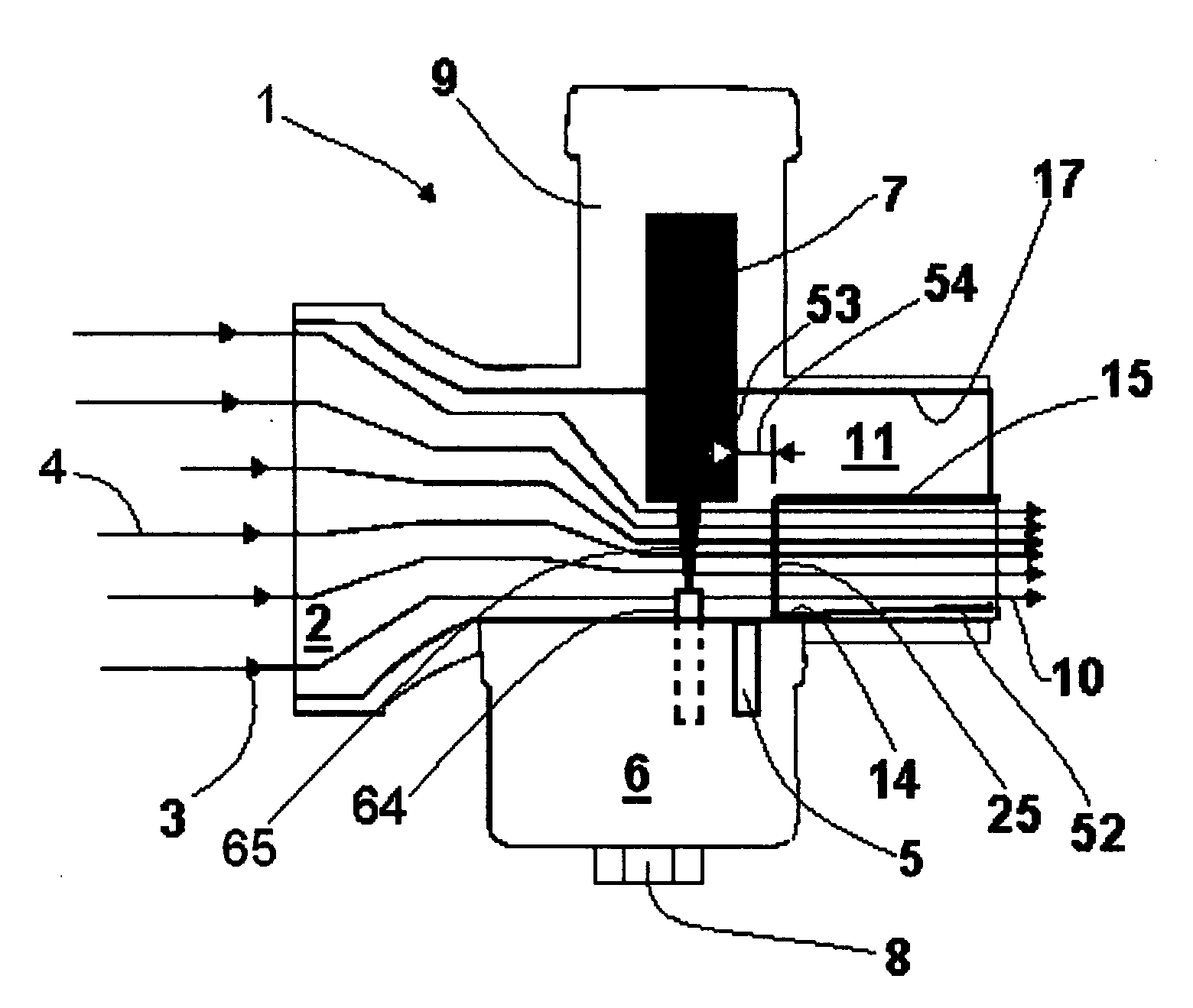
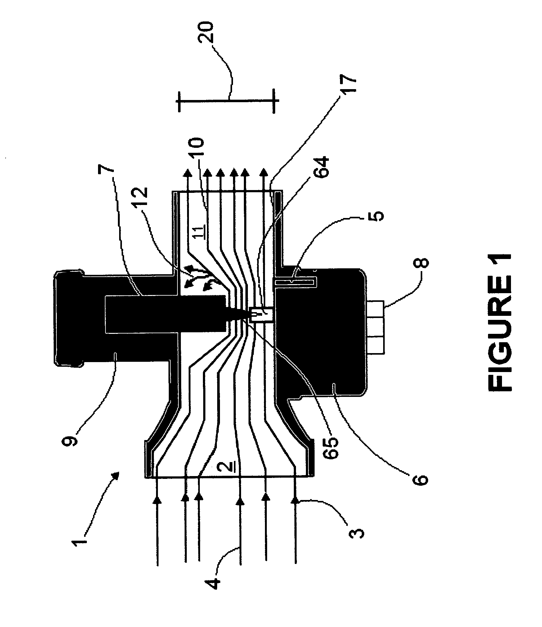
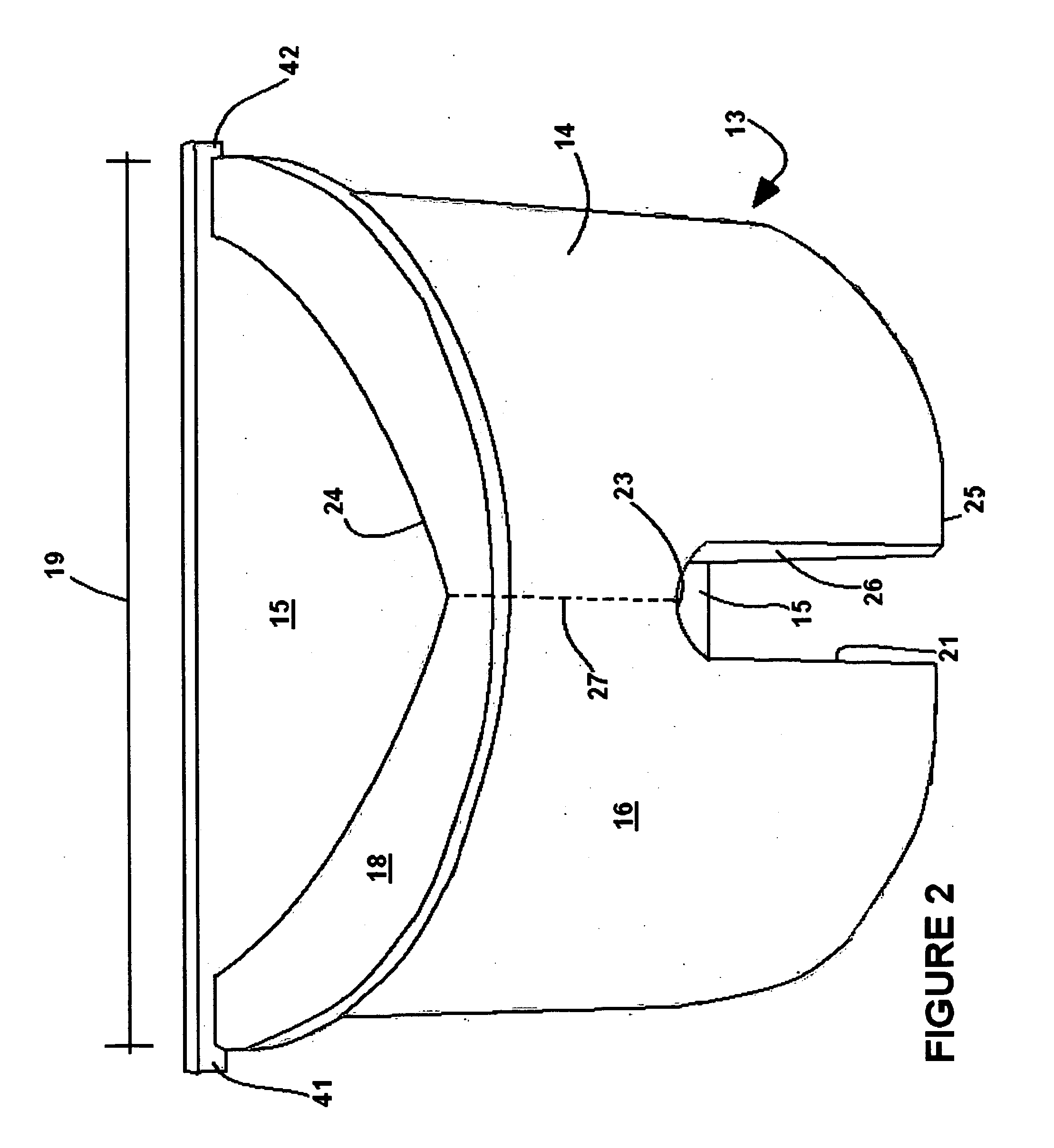
[0030] Referring generally to FIG. 2, the carburetor insert 13 of the present invention is seen to include a venturi component 14 and an airfoil or wing component 15. The venturi 14 is formed to have an outer wall 16 shaped generally as a semicircular cylinder that is dimensioned to fit snugly within the cylindrical bore 17 of a carburetor 1. The venturi 14 includes a lip 18 that has an outer diameter 19 somewhat greater than the inner diameter 20 of bore 17. The venturi 14 is intended to be inserted into the bore 17 and the lip 18 provides a positive mechanism for preventing insertion beyond the desired point. Further, the venturi 14 includes a cutout or void region 21 which is intended to provide clearance for the carburetor pilot fuel jet 5. If the venturi 14 were to be inserted too far into the bore 17, the edge 23 of the cutout 21 might collide with and damage the fuel jet 5.

[0031] The venturi 14 may be composed of any rigid, fuel resistant material such as metal or plastic. A...


PUM

PropertyMeasurementUnit
angleaaaaaaaaaa
angleaaaaaaaaaa
angleaaaaaaaaaa

Abstract

A carburetor (1) having an existing venturi upstream of a throttle plate (7) and a bore (17) downstream of a throttle plate (7) is provided with a second venturi (14) which increases airflow velocity and promotes fuel atomization. An aerodynamic piece or wing (15) is mounted to the top of the venturi to further define the airflow path and to prevent the downstream fuel / air mixture (10) from losing velocity after passing the throttle plate. The wing (15) includes a first set of tabs (41, 42) to secure the wing to the engine intake manifold and as second set of tabs (43, 44) to secure the combined wing (15) and venturi to an oversized carburetor bore. A cutout (21) in the venturi (14) prevents interference with the carburetor fuel jet (5). The wing (15) may be formed with a specially shaped trailing edge (51) in order to accommodate the contours of the throttle plate.

Description

FIELD OF THE INVENTION [0001] The present invention relates generally to the field of carburetion, and more particularly to the field of carburetor venturi structures and accessories. DESCRIPTION OF RELATED TECHNOLOGY [0002] A carburetor is a device for mixing air and fuel in an internal combustion engine in order to provide a combustible fluid for introduction into a cylinder or other combustion chamber. The carburetor typically has a central bore that is obstructed by a throttle plate which, depending upon the position of the throttle plate admits relatively more or less of the fuel / air mixture into the subsequent or downstream venturi portion of the carburetor. For relatively higher powered engines, the carburetor bore is relatively larger in diameter because a relatively greater amount of fuel and air is needed to support the combustion process that generates the higher power. However, at relatively lower throttle settings, a large bore carburetor becomes relatively inefficient ...

Claims


Application Information

Patent Timeline
Patent Type & Authority Applications(United States)
IPC IPC(8): F02M19/10
CPCF02M19/105
Inventor PETERSON, LONN M.
Owner PETERSON LONN M
Why Eureka
Eureka Blog
Learn More