Optical reading apparatus

Inactive Publication Date: 2006-10-26
LITE ON IT
View PDF4 Cites 0 Cited by
  • Summary
  • Abstract
  • Description
  • Claims
  • Application Information

AI Technical Summary

Benefits of technology

[0007] Therefore, an object of the present invention is to design an optical reading apparatus for conveniently adjusting the amplitude of the high frequency modulating signal so as to reduce the EMI effect and thus improve the data-reading quality.
[0008] Another object of the present invention is to design an optical reading apparatus for well distributing the frequency of the high frequency modulating signal so as to reduce the EMI effect and thus improve the data-reading quality.

Problems solved by technology

Therefore, the resulting electronic signal generated by the photodiode 12 would be adversely affected by the interference and the data reading / writing accuracy would thus be deteriorated.
However, the HFM technology is likely to cause some problems.
Unfortunately, the higher the amplitude of high frequency modulation signal is, the more significant the electromagnetic interference (EMI) of the optical disc drive is.
Accordingly, the high-frequency modulating signal with too high amplitude would cause the optical disc drive fails in the EMI test.
The process of replacing resistors would be too complicated to be cost- and laboring-efficient.

Method used


Image

  • Optical reading apparatus
  • Optical reading apparatus
  • Optical reading apparatus

Examples


Embodiment Construction

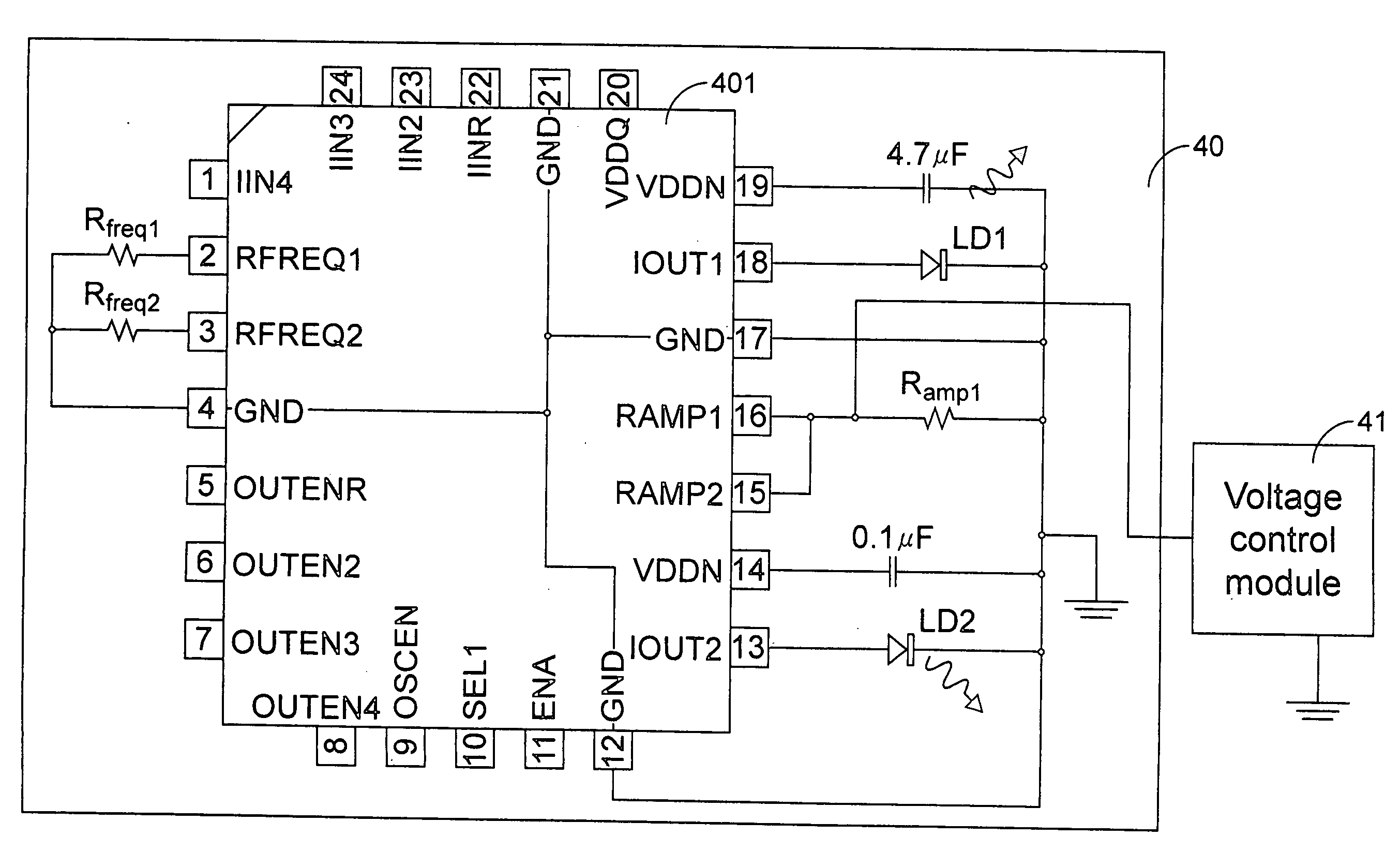
[0025] In an embodiment of an optical reading apparatus shown in FIG. 4, the circuitry coupled to a high-frequency modulator IC 401 similar to the high-frequency modulator IC 3 of FIG. 3(a) includes laser diodes LD1 and LD2 coupled to both pin numbers 18 and 13 of the IC 401, a resistor Ramp1 coupled to both pin numbers 15 and 16 of the IC 401, and a voltage control module 41 coupled to pin numbers 15 and 16 of the IC 401 in parallel to the resistor Ramp1 but disposed outside the optical pickup unit 40. Laser diodes LD1 and LD2 are used as light sources for emitting laser beams with different wavelength to read different kinds of optical discs, e.g. CD and DVD, respectively. The intensity of the light beam emitted by laser diode LD1 or LD2 is adjusted by superimposing a high-frequency modulation signal outputted by the IC 401 on the driving current of the laser diode LD1 or LD2. Since the voltage control module 41 is coupled to the node of pin numbers 15 and 16, the output current v...


PUM


Abstract

In an optical reading apparatus, a light source, a high frequency modulator IC and a first resistor are integrated in an optical pickup unit, wherein the light source emits a light beam onto the optical storage medium in order to read information from the optical storage medium, the high frequency modulator generates a high frequency modulating signal for adjusting the intensity of the light beam, and the first resistor has a first end coupled to ground and a second end couple to a first pin of the high frequency modulator IC. A voltage control module disposed outside the optical pickup unit and coupled to the first resistor in parallel is used for adjusting an output current of the first pin in response to a voltage change thereof, thereby adjusting the amplitude of the high frequency modulating signal.

Description

FIELD OF THE INVENTION [0001] The present invention relates to an optical reading apparatus such as an optical disc drive, and more particularly to an optical reading apparatus adopting high frequency modulation. BACKGROUND OF THE INVENTION [0002]FIG. 1 shows an optical pickup unit (OPU) of a typical optical disc drive. A light beam emitted from a laser diode 10 is focused on the surface of an optical disk 1 through an optical system 11 including a set of lens and mirrors. The reflected light beam from the optical disk 1 through the optical system 11 is converted to an electronic signal by a photodiode 12. The incident and reflective light paths in the OPU of FIG. 1 are separately shown in the FIG. 2(a) and 2(b). As shown in FIG. 2(a), the incident light beam is emitted from the laser diode 10 and transmitted through the optical system 11 to reach the surface of the optical disk 1. Afterwards, as shown in FIG. 2(b), the light beam carrying information of the optical disc 1 is reflec...

Claims


Application Information

Patent Timeline
IPC IPC(8): G11B7/00G11B7/12G11B7/125
CPCG11B7/126G11B7/1205G11B7/123
Inventor HSU, JEN-YUFU, HSIANG-YICHEN, FU-HSIANGTSAI, MING-HSIAO
Owner LITE ON IT
Why Eureka
Try Eureka