Optical switch
a technology of optical switches and switches, applied in the field of optical switches, can solve the problem of relatively large size of optical switches, and achieve the effect of reducing the size of the apparatus
- Summary
- Abstract
- Description
- Claims
- Application Information
AI Technical Summary
Benefits of technology
Problems solved by technology
Method used
Image

Examples
first embodiment
Description of First Embodiment
Structure
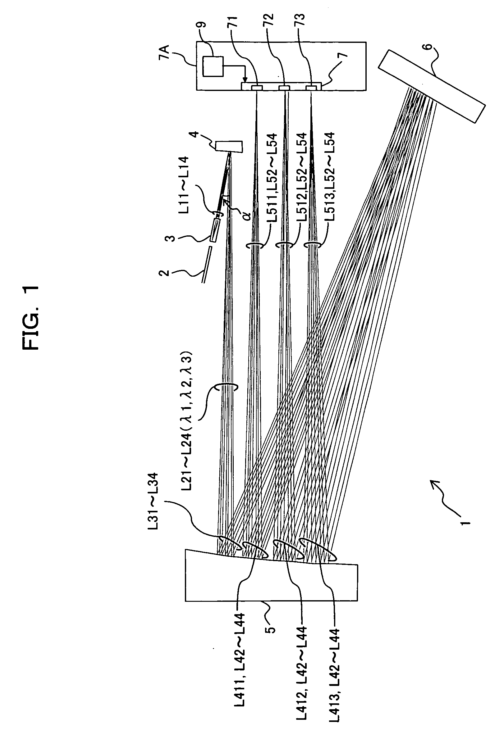
[0042]FIG. 1 is a top schematic view showing an optical switch 1 according to a first embodiment of the present invention. The optical switch 1 shown in FIG. 1 has a function capable of selectively outputting an input wavelength-multiplexed signal to an arbitrary output port for each wavelength, and comprises a fiber array 2, a collimate lens array 3, a convex mirror 4, a concave mirror 5, a diffraction grating 6 and a MEMS mirror array 7. The first embodiment assumes that when a wavelength-multiplexed signal having three kinds of center wavelengths λ1 to λ3 is input from one input port, the components of these wavelengths λ1 to λ3 are output to output ports, respectively.
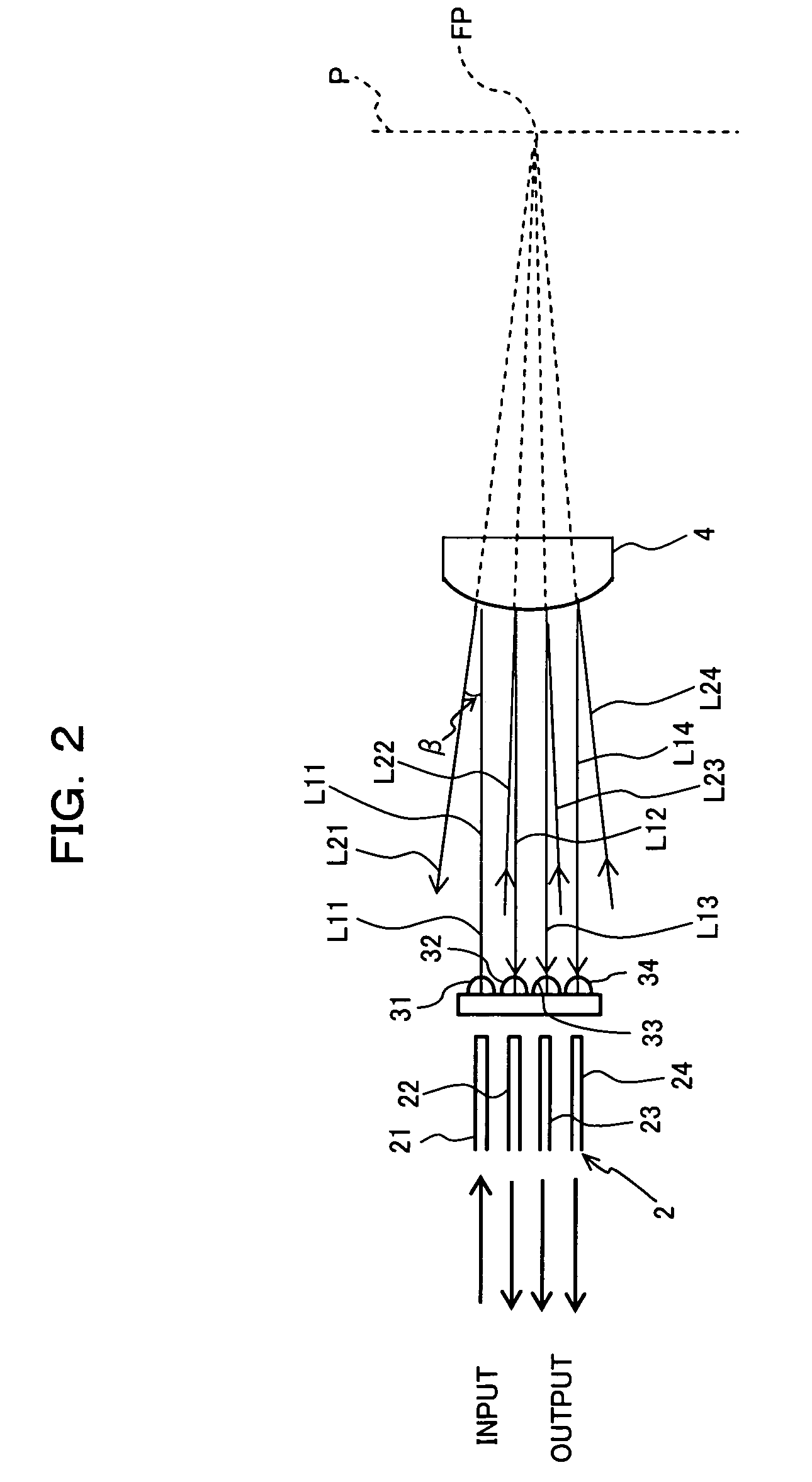
[0043]FIG. 2 is a front schematic view mainly showing the fiber array 2, the collimate lens array 3 and the convex mirror 4 constituting the optical switch 1 in FIG. 1, and FIGS. 3(a) to 3(c) show an equivalent optical system where the optical systems constituting the opti...
second embodiment
Description of Second Embodiment
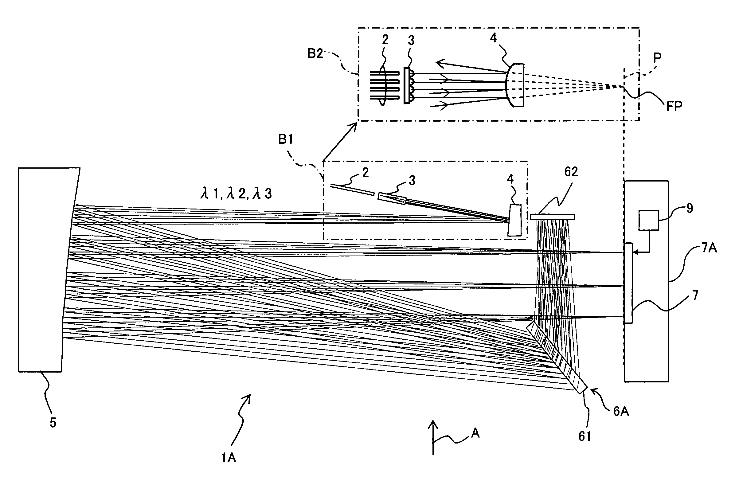
[0067]FIG. 4 is a top schematic view showing an optical switch 1A according to a second embodiment of the present invention. The optical switch 1A shown in FIG. 4 is different from the optical switch 1 according to the first embodiment in the structure as the diffraction grating unit, but is basically similar thereto in other structure. In FIG. 4, like numerals identical to those in FIG. 1 denote substantially like portions, and a portion B2 surrounded by a dashed line in the figure illustrates a portion B1 similarly surrounded by a dashed line (the optical fiber array 2, the collimate lens array 3 and the convex mirror 4) from the direction of an arrow A and corresponds to FIG. 2.
[0068] A diffraction grating unit 6A is constituted of a transmission diffraction grating 61 and a reflecting mirror 62. The reflecting mirror 62 is a third reflecting member for reflecting a light transmitting through the transmission diffraction grating 61 and returning t...
third embodiment
Description of Third Embodiment
[0073]FIG. 5 is a top schematic view showing an optical switch 1B according to a third embodiment of the present invention. The optical switch 1B shown in FIG. 5 is different from the optical switch 1A shown in FIG. 4 in that a structure of a reflecting mirror 62B constituting a diffraction grating unit 6B is different from the reflecting mirror 62B as the corresponding constituent in FIG. 4 and an optical device 8 for expanding a beam diameter of an input light is provided between the collimate lens array 3 and the convex mirror 4. Other structure is substantially identical to that according to the second embodiment, and in FIG. 5, like numerals identical to those in FIG. 4 denote substantially like portions.
[0074] The optical device 8 is directed for changing a beam shape from a Gaussian beam shape to an elliptical shape such that the beam diameter expands in a direction in which a wavelength-multiplexed light as an input light is spectrally diffrac...
PUM
 Abstract
Description
Claims
Application Information
 - Generate Ideas
- Intellectual Property
- Life Sciences
- Materials
- Tech Scout
- Unparalleled Data Quality
- Higher Quality Content
- 60% Fewer Hallucinations
Browse by: Latest US Patents, China's latest patents, Technical Efficacy Thesaurus, Application Domain, Technology Topic, Popular Technical Reports.
© 2025 PatSnap. All rights reserved.Legal|Privacy policy|Modern Slavery Act Transparency Statement|Sitemap|About US| Contact US: help@patsnap.com