
Pump

a technology of pumping and ball bearings, applied in the field of pumps, can solve the problems of inability to expect the lubrication of liquid being pumped, the wear of bearings is severe, so as to reduce the centrifugal force, enhance the corrosion resistance of cleaning agents, and ensure reliability.

Active Publication Date: 2006-10-26
MITSUBISHI HEAVY IND LTD
View PDF7 Cites 18 Cited by
  • Summary
  • Abstract
  • Description
  • Claims
  • Application Information

AI Technical Summary

Benefits of technology

[0026] In accordance with the present invention, a pump for carrying supercritical CO2 fluid or liquid CO2, capable of securing reliability by optimizing a bearing part can be supplied.
[0027] Specifically, by employing a totally ceramic bearing, it is possible to enhance the corrosion resistance against a cleaning agent. Additionally, it is possible to reduce a centrifugal force due to high-speed rotation, enhance wear resistance and prevent damages caused by particles coming from the outside.
[0028] Moreover, by reducing the drag loss of the cage, damages caused by the revolution skidding of a bearing can be prevented. Also, by enhancing the characteristic of the revolution skidding, the preload can be decreased, which reduces the thrust load, thereby achieving extension of operating life of the bearing. Additionally, by decreasing the drag loss, efficiency of the pump can be enhanced.
[0029] For the rest, by optimizing the ratio of the ball diameter versus the radius of the orbit slot (ratio of the slot radius), seize resistance can be improved and at the same time, extension of ope

Problems solved by technology

Because ball bearings are used in supercritical CO2 (or liquid CO2) of low viscosity, lubrication by liquid being pumped cannot be expected and the environmental condition is severe for the wear of the bearings.
Therefore, there is a concern of corrosion and the like of the ball bearings being caused by chemicals.

Method used


Image

  • Pump
  • Pump
  • Pump

Examples


Embodiment Construction

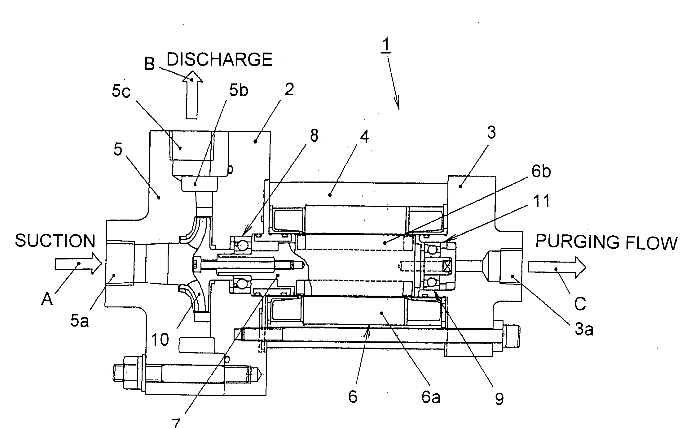
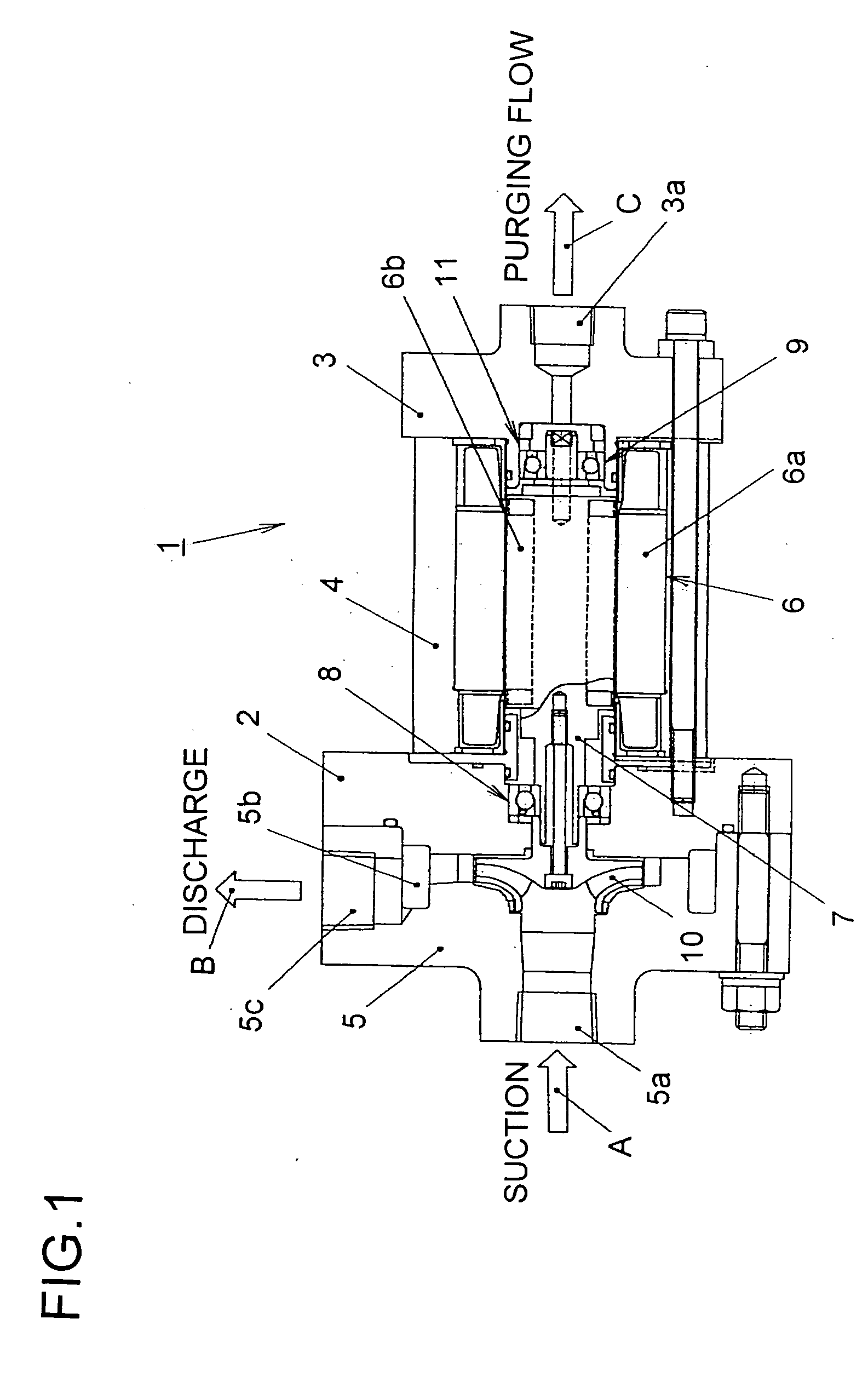
[0051] Referring now to the drawings, an embodiment of the present invention will be described hereinafter. FIG. 1 is a cross-sectional view showing the construction of a CO2 pump in accordance with an embodiment of the present invention. A pump 1 comprises a discharge / suction-side casing 2, a purging-side casing 3 and an outer cylinder 4 being held therebetween. Outside the suction / discharge-side casing 2 is installed a manifold 5 which sucks and discharges the liquid being pumped.

[0052] Inside the outer cylinder 4 is installed a canned motor 6 which drives the pump 1, comprising a stator 6a outside thereof and a rotor 6b being housed inside the stator 6a. The rotor 6b is installed to a main shaft 7; and the main shaft 7 is supported on both ends thereof by an angular ball bearing 8 being installed to the discharge / suction-side casing 2 and an angular ball bearing 9 being installed to the purging-side casing 3 so as to rotate, specifically, being axially supported.

[0053] Between ...


PUM

PropertyMeasurementUnit
Fractionaaaaaaaaaa
Timeaaaaaaaaaa
Radiusaaaaaaaaaa

Abstract

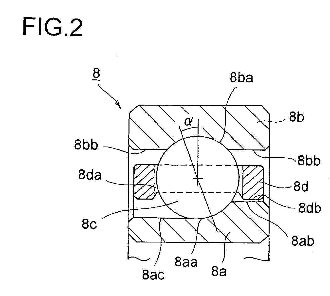
A pump for carrying supercritical CO2 fluid or liquid CO2 capable of securing reliability by optimizing a bearing part. An angular ball bearing (8) comprises an inner ring (8a), an outer ring (8b), balls (8c) held therebetween, and a cage (8d) holding the balls (8c). Both the balls and the inner and outer rings are formed of a ceramic to form a totally ceramic bearing. Also, the cage (8d) is guided by the outer ring or the inner ring. Specifically, for example, when the cage is guided by the inner ring, the inner peripheral surface (8db) of the cage (8d) opposed to the outermost peripheral surface (8ab) of the inner ring (8a) is guided by the outermost peripheral surface (8ab) of the inner ring (8a).

Description

TECHNICAL FIELD [0001] The present invention relates to a pump which carries supercritical CO2 fluid or liquid CO2. BACKGROUND ART [0002] Because supercritical fluid can continuously change the volume (density) thereof by regulating the temperature and pressure, values of various properties such as dissolution characteristic and the like can be easily controlled, which makes it possible to utilize supercritical fluid as a refrigerant. Additionally, because the viscosity thereof is low but the diffusivity thereof is high, supercritical fluid is expected to be used for washing; or is expected to be used as a refrigerant because the thermal conductivity thereof is high. [0003] Being easy to get and good in handling and the like because of not having explosive nature, inflammability and the like, water, CO2 and the like are generally used as supercritical fluid. Especially, CO2 has characteristics that the critical temperature is 31° C. and the critical pressure is 7.38 Mpa; that the te...

Claims


Application Information

Patent Timeline
IPC IPC(8): F04B17/00F04D29/047F04B53/00F04D13/06F04D29/04F04D29/049F16C19/16F16C33/30F16C33/32F16C33/38F16C33/44F16C33/62
CPCF04D29/049F16C19/163F16C33/30F16C2206/60F16C2300/42F16C2360/42F16C33/3856F16C2208/36
Inventor YAMAMOTO, YASUHARUOSADA, TOSHIYUKIYOSHIDA, TAKAFUMIKAIKOGI, TAKAAKIMINAMI, MASAHARU
Owner MITSUBISHI HEAVY IND LTD
Learn More