Method for imaging of a periodically-moving subject region of a subject

a subject and subject technology, applied in the field of subject imaging, can solve the problems of limited use of navigator techniques, limited spatial resolution, and limited real-time method, and achieve the effect of simple administration, robust manner, and fast and accurate results

Inactive Publication Date: 2006-10-26
SIEMENS AG
View PDF6 Cites 25 Cited by
  • Summary
  • Abstract
  • Description
  • Claims
  • Application Information

AI Technical Summary

Benefits of technology

[0009] An object of the present invention is to provide a method for imaging a periodically-moving subject region that is simple to administer and proceeds quickly and in a robust manner.
[0011] In comparison to a fixed slice positioning in the imaging of the moving subject region, a higher diagnostic value of the image data results because the subject region is imaged in its full movement. Relative to a manual positioning of all individual slices, a significant time savings results for the user. Since no navigator techniques are used in the present method, the image generation is shorter overall. Moreover, it is not necessary to evaluate a contrast change in order to determine the current movement state. The placement of the slice can ensue directly on the desired anatomy. A tagging-based reference scan can also be used as an overview image data set that can be combined for visual orientation in the event that the positioning of the slices at various points in time is possible in an easy manner on the basis of a shifting tagging pattern.

Problems solved by technology

Since the achievable spatial resolution is currently very limited in the real-time method, in many applications the only way to achieve a diagnostic image quality is to use segmented acquisition methods.
These methods, however, normally enable only slice tracking perpendicular to a fixed slice orientation.
A disadvantage of these techniques is that a portion of the acquisition time must be devoted to the acquisition for the navigator signal.
The use of the navigator techniques then can be limited in part.
The suitable slice geometries (thus the position and orientation of the slice to be acquired) for all heart phases can be extracted with a dynamic image analysis, but limitations exist with regard to the positioning of the tagging pattern.
An alternative, manual positioning of all (typically 20 to 30) slices for the primary measurement is not acceptable from the viewpoint of the operator and workflow because this takes too long the large number of slices can be placed accurately relative to one another only with difficulty.

Method used


Image

  • Method for imaging of a periodically-moving subject region of a subject
  • Method for imaging of a periodically-moving subject region of a subject
  • Method for imaging of a periodically-moving subject region of a subject

Examples


Embodiment Construction

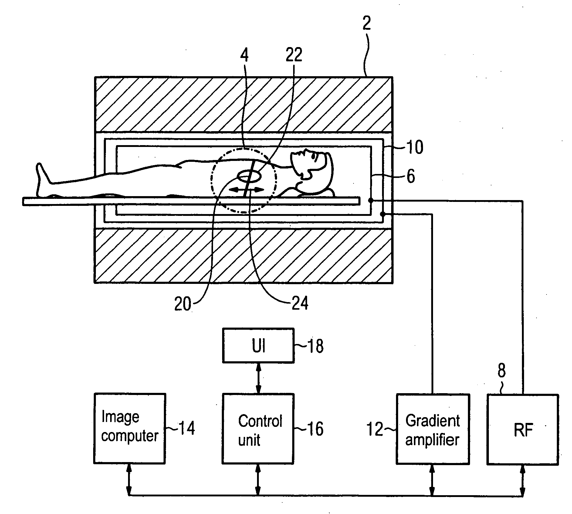
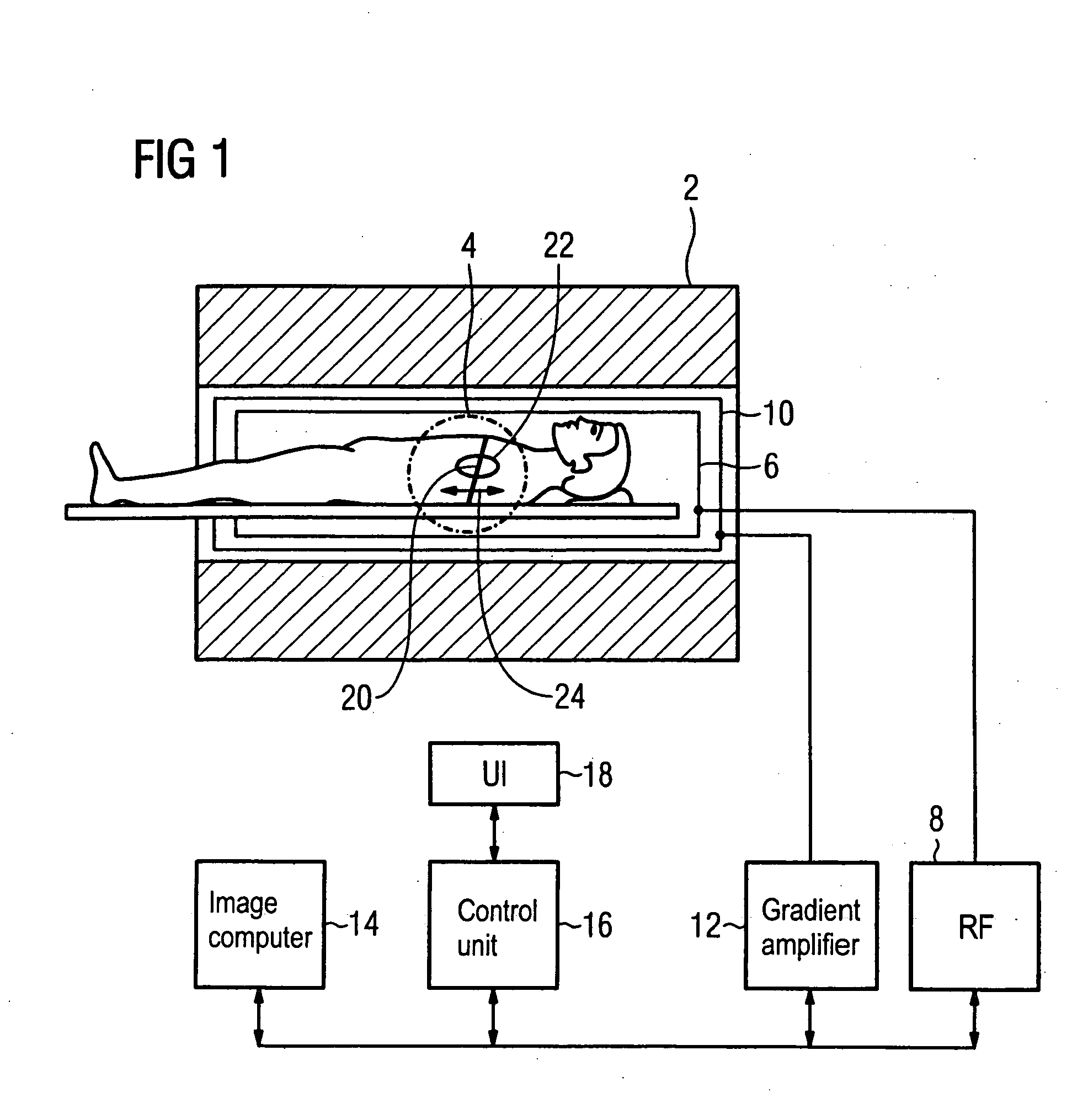
[0019]FIG. 1 shows the design of a diagnostic magnetic resonance apparatus with which imaging of a moving subject region of a moving subject can be implemented. The magnetic resonance apparatus has a conventional design except its controller is designed for execution of an embodiment of the inventive method.

[0020] Since the basic design of a diagnostic magnetic resonance apparatus as well known, here only the basic functional components are mentioned in brief summary. The magnetic resonance apparatus comprises a superconducting magnet 2 that generates a constant and homogeneous magnetic field in an imaging region 4 in its cylindrical inner chamber. A radio-frequency antenna unit 6 for excitation and reception of magnetic resonance signals is located in the cylindrical inner chamber. The radio-frequency antenna unit 6 is connected with a radio-frequency transmission and reception unit 8. A gradient coil unit 10 for spatially coding the magnetic resonance signals with temporally- and...


PUM


Abstract

In a method for imaging a periodically-moving subject region of a subject, an overview image data set is initially obtained that maps a movement of the subject region, at least two positions that the subject region assumes at corresponding points in time are marked in the overview image, further positions of the subject region at further points in time are interpolated from the marked positions and further points in time, and a subsequent diagnostic imaging of the moving subject region is implemented using the marked and interpolated positions.

Description

BACKGROUND OF THE INVENTION [0001] 1. Field of the Invention [0002] The present invention concerns a method for imaging a periodically-moving subject region of a subject, in particular a method for medical imaging of moving organs. [0003] 2. Description of the Prior Art [0004] The demands on imaging methods for moving organs are high. In order to distinctly map moving regions, in addition to a good spatial resolution the imaging method must also possess a sufficient temporal resolution. If slower imaging methods are used for specific reasons such as, for example, a high spatial resolution, the acquisition region for the imaging can be guided along corresponding to the movement. The use of correction methods in the post-processing of the acquired image data is also known. [0005] Sequences that can acquire the movement of an imaging slice with sufficiently-high temporal resolution are used today for dynamic magnetic resonance imaging of moving organs such as, for example, the heart. T...

Claims


Application Information

Patent Timeline
Patent Type & Authority Applications(United States)
IPC IPC(8): A61B5/05
CPCA61B5/055G06T2211/412G06T11/005G01R33/563
Inventor GREISER, ANDREASLANDSCHUTZ, WILFRIEDSPEIER, PETER
Owner SIEMENS AG
Why Eureka
Try Eureka