Ultrasonic probe for scanning a volume

a volume scanning and ultrasonic technology, applied in the field of ultrasonic probes, can solve the problems of complex design and assembly of matrix array transducer devices, different design and assembly difficulties of rotating and swinging probe devices, and achieve the effect of minimizing resistance forces and avoiding undesirable acoustic effects

Active Publication Date: 2006-10-26
VERMON
View PDF3 Cites 23 Cited by
  • Summary
  • Abstract
  • Description
  • Claims
  • Application Information

AI Technical Summary

Benefits of technology

[0024] One aspect of the invention relates to the provision of an integrated construction wherein an otherwise conventional front lens of an imaging transducer includes an extended portion or lip which is sealed to the probe front housing or case so as to form a separation wall between the coupling fluid of the liquid bath and the exterior of the housing in such a manner as to avoid undesirable acoustic effects associated with conventional separation membranes which are typically disposed over the transducer surface, as well as to overcome any fluid leaking problem due to the presence of bonding joints between the transducer and the membrane.
[0025] A further aspect of the invention concerns the provision of a method for shaping the extended portion or lip of the lens in the space separating the transducer and the probe housing or case so as to minimize resistance forces occurring at extreme positions of the transducer.

Problems solved by technology

Although the first, matrix array approach definitely provides major advantages in comparison with moving probes, the design and assembly of matrix array transducer devices turns out to be quite intricate, especially in terms of the repeatability and homogeneity of the pixels.
In addition, the required electrical matching of each pixel to the transmission line also presents problems.
In practice, rotating and swinging probe devices are characterized by different design and assembly difficulties.
In this regard, the non-uniform distance separating the transducer from the case shell strongly affects the homogeneity of the probe output.
The amount of attenuation varies with the distance and the resultant impedance mismatches (sound speed and density) produce deviations in the transducer radiation pattern which contribute to an increase in side lobe levels and to focal aberrations.
Further, the liquid partition membrane, which is provided as an add-on device over the front surface of the transducer, causes image artifacts and produces attenuation of the acoustic energy.
This constraining force will result in non-uniform transducer movement so that the overall system must be implemented with a real time position correction algorithm.
While a probe apparatus is well adapted for a conventional 3D imaging process wherein the transducer is incrementally stopped in a first position to effect acquisition of an image and then is stepped up to the next position to effect acquisition of a further image, this method is not, however, compatible with “on-the-fly” 3D imaging processing wherein the volumetric information is instantly available during probe operation and wherein the transducer movement must be accurately correlated with the images being acquired.
Major drawbacks suffered by the Biophysic Medical scanner apparatus include, first, the assembly method required for attaching the membrane to the transducer case is unreliable and the resultant membrane attachment is subject to leaking of the fluid.
Second, the required positioning of the membrane increases the effort that must be provided by the motor when the transducer reaches the extreme positions of the swinging movement thereof.

Method used


Image

  • Ultrasonic probe for scanning a volume
  • Ultrasonic probe for scanning a volume
  • Ultrasonic probe for scanning a volume

Examples


Embodiment Construction

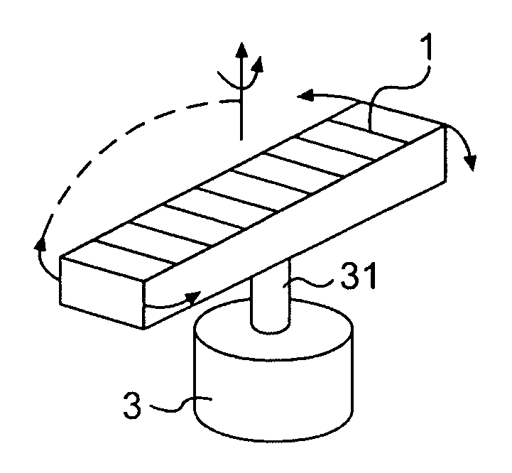
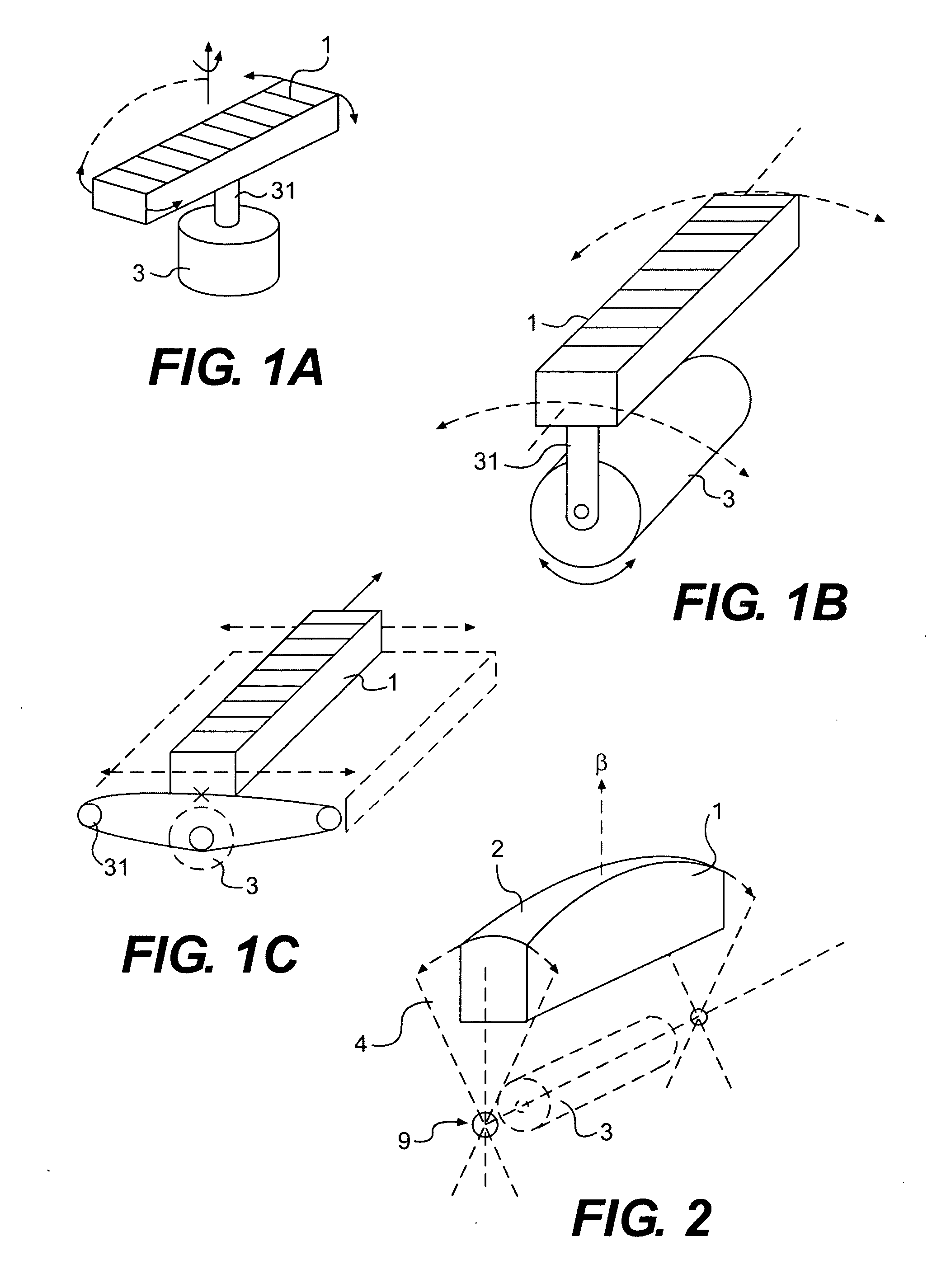
[0035]FIGS. 1A to 1C, in which the same reference numerals are used to denote similar elements, depict currently used prior art devices and illustrate conventional methods for moving an array transducer in order to obtain volume information. The array transducer 1 is used to provide planar electronic scanning images (i.e., 2D images) while the movement of the transducer 1 completes the acquisition of volume information.

[0036] In FIG. 1A, transducer 1 rotates in alternating fashion under the control of an energizing of motor 3 which is connected to the transducer 1 by a motor shaft 31. The transducer I is coupled to the motor shaft 31 at its center of symmetry so as to simplify rendering of the volume information. The direction of acoustic energy propagation from transducer 1 is controlled by rotation of the transducer 1 about the vertical axis that is superimposed on the axis of symmetry of transducer 1. This method of scanning is well developed and is convenient for use with movin...


PUM


Abstract

An ultrasonic imaging probe is provided which is capable of capturing “on-the-fly” scanning planes in successive positions of the probe so as to form a volumetric image representation at a real time frame rate. The probe includes a flexible sealing membrane for a coupling fluid. Laterally extending folding portions of the flexible membrane provide fluid isolation and cancellation of parasitic constraining forces normally generated during probe movement.

Description

BACKGROUND OF THE INVENTION [0001] 1. Field of the Invention [0002] The invention relates to ultrasonic probes used for volumetric scanning and, more particularly, to an ultrasonic imaging probe capable of capturing “on-the-fly” scanning planes in successive positions so as to form a volumetric image representation at a real time frame rate. [0003] 2. Related Art [0004] Ultrasonic scanners and probes for acquiring and processing volume information related to biologic tissue or a living body are well known in the art. In the early 1980s, the three-dimensional visualization of human fetus began using systems employing mechanical equipment and basic algorithms for volume rendering. It is believed that these systems are the first 3D imaging systems that use a linear array transducer mounted on a position-sensing arm and capable of providing the system with information regarding the spatial position of the transducer. This approach requires complex mechanical equipment and has now been a...

Claims


Application Information

Patent Timeline
Patent Type & Authority Applications(United States)
IPC IPC(8): A61B8/00
CPCA61B8/00G01S15/8993G01S15/8938A61B8/483
Inventor NGUYEN-DINH, ANFLESCH, AIMEDUFAIT, REMIAUCLAIR, PHILIPPE
Owner VERMON
Why Eureka
Try Eureka