Intravascular ultrasound catheter device and method for ablating atheroma

a catheter device and intravascular ultrasound technology, applied in the field of medical devices, to achieve the effect of prolonging time-integrated emulsification, increasing its effectiveness, and prolonging time-integrated emulsification

Inactive Publication Date: 2006-10-26
YU QI
View PDF26 Cites 53 Cited by
  • Summary
  • Abstract
  • Description
  • Claims
  • Application Information

AI Technical Summary

Benefits of technology

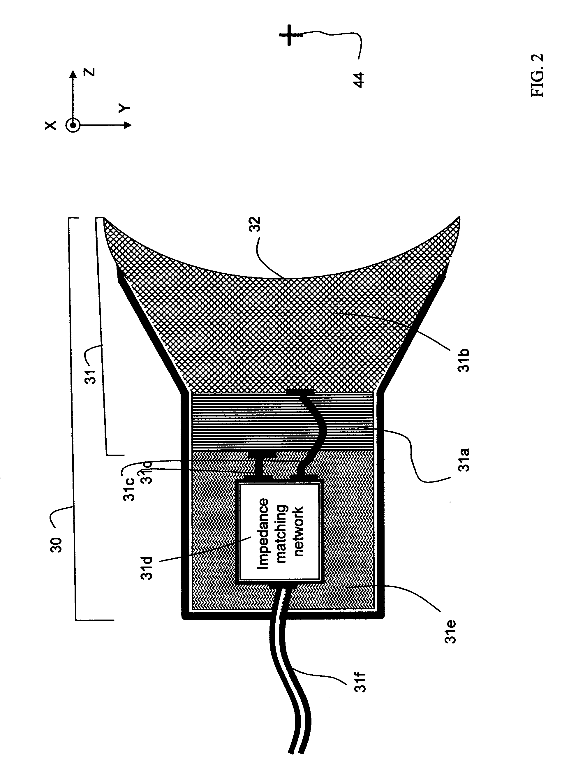
[0028] The leaky acoustic cavity can further include a trapping and emulsification device, disposed within and around the ultrasound ablation manifold, to trap larger sized plagues and calcified tissue fragments created by both extra-cavity ablation and intra-cavity ablation. This will prolong time-integrated emulsification and reabsorption into the body thereafter without clogging up the downstream capillaries.
[0029] In one embodiment, the trapping and emulsification device includes a trapping manifold located interior to the bird cage and having a multitude of well-placed physical barriers adapted to occlude or impede the movement of the larger sized plagues and calcified tissue fragments. The multitude of physical barriers can be made of circular or rectangular grid of thin wires, supported by the bird cage, whose wire diameter is made small enough to not impede the propagation of the ultrasonic power emission. In another embodiment, the trapping and emulsification device is the combination of the bird cage and the protective shield hence making the combination multi-functional. In yet another embodiment, the trapping and emulsification device can be a fluid pumping device located inside the ultrasound ablation manifold for creating a local blood vortex sucking the larger sized plagues and calcified

Problems solved by technology

The recirculating blood delivering and injecting unit can also administer drugs designed for treating a l

Method used


Image

  • Intravascular ultrasound catheter device and method for ablating atheroma
  • Intravascular ultrasound catheter device and method for ablating atheroma
  • Intravascular ultrasound catheter device and method for ablating atheroma

Examples


Embodiment Construction

[0052] In the following detailed description of the present invention, numerous specific details are set forth in order to provide a thorough understanding of the present invention. However, it will become obvious to those skilled in the art that the present invention may be practiced without these specific details. In other instances, well-known methods, procedures, materials, components and circuitry have not been described in detail to avoid unnecessary obscuring aspects of the present invention. The detailed description is presented largely in terms of simplified two dimensional views. These descriptions and representations are the means used by those experienced or skilled in the art to concisely and most effectively convey the substance of their work to others skilled in the art.

[0053] Reference herein to “one embodiment” or an “embodiment” means that a particular feature, structure, or characteristics described in connection with the embodiment can be included in at least on...


PUM


Abstract

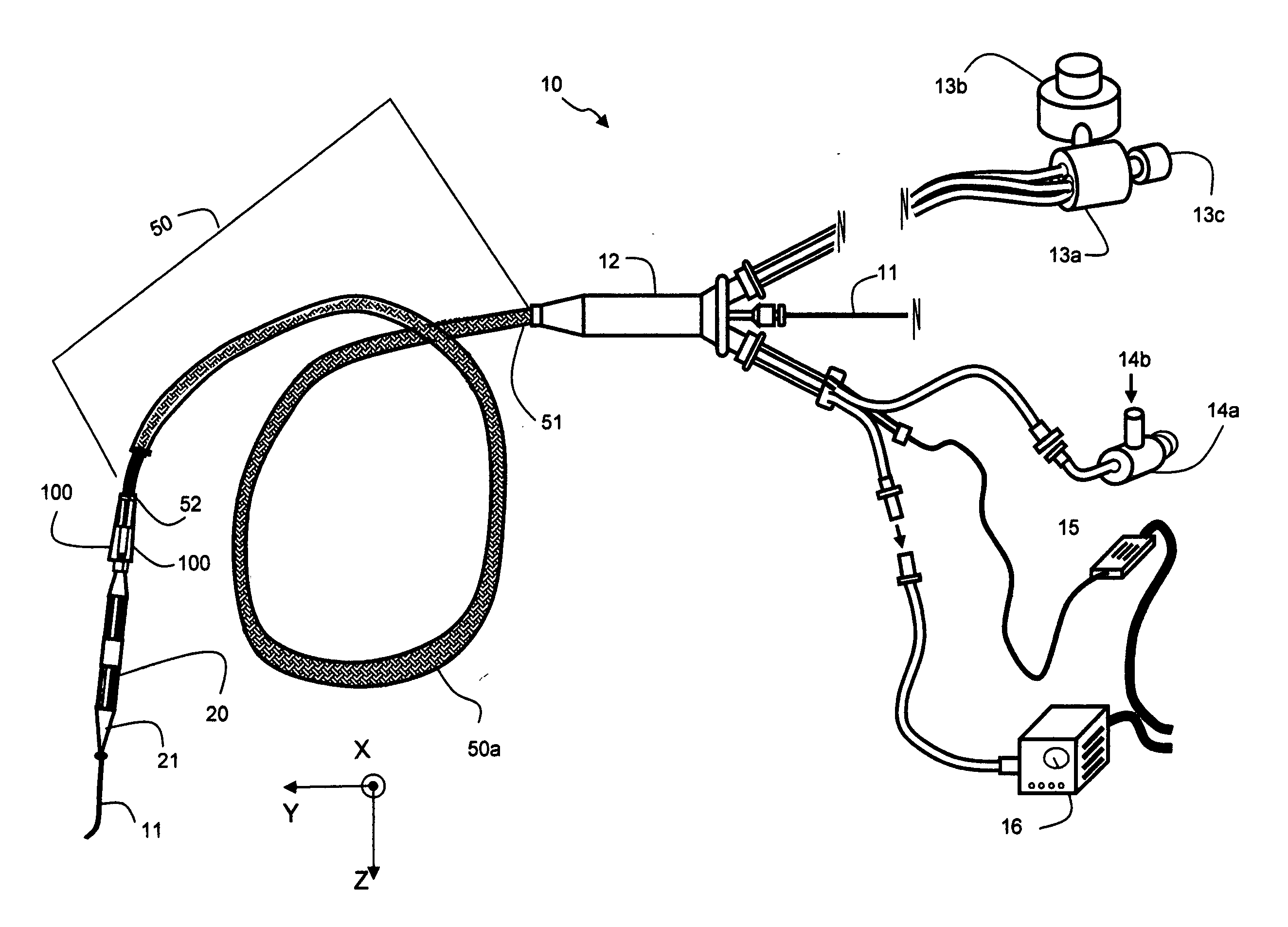
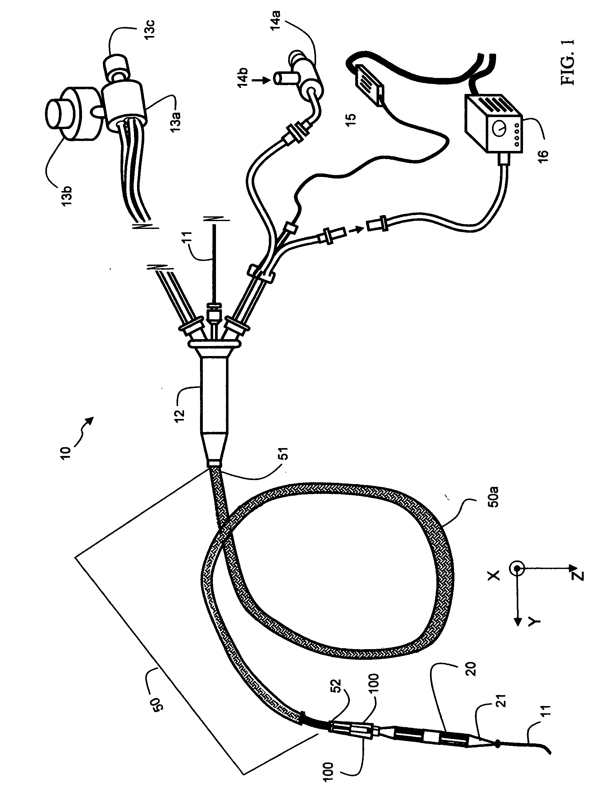
An intravascular catheter device having a catheter and an ultrasound ablation manifold is proposed for generating cavitations and acoustic jet streams in the blood to ablate atheroma. The ablation manifold has a power transducer and a coupled leaky acoustic cavity. The leaky acoustic cavity contains a first portion of ultrasonic power emission for intra-cavity ablation while allowing a second portion of ultrasonic power emission to leak outside for an extra-cavity ablation. The power transducer and the leaky acoustic cavity are configured to form a confocal resonant cavity. An intervening bird cage is coupled to the resonant cavity for stronger resonance while maintaining ultrasound leakage. A protective shield is mounted around the waist of bird cage to strengthen resonance and to prevent damaging the intima from an otherwise normal incidence of high intensity ultrasound. A microbubble releasing device and micro pump are also included to further increase the ablation efficacy.

Description

CROSS REFERENCE TO RELATED APPLICATION [0001] This application is a continuation-in-part of U.S. patent application Ser. No. 11 / 077,942, filed Mar. 11, 2005, which is incorporated herein by reference in its entirety and for all purposes.BACKGROUND OF THE INVENTION [0002] 1. Field of the Invention [0003] The present invention relates generally to the field of medical apparatus. More particularly, this invention relates to an intravascular ultrasound catheter device for ablating undesirable deposits from an inner blood vessel wall. [0004] 2. Description of the Related Art [0005] See corresponding section from U.S. patent application Ser. No. 11 / 077,942. SUMMARY OF THE INVENTION [0006] An intravascular ultrasound catheter device is proposed for ablating undesirable blood vessel deposits. The apparatus includes a recirculating blood delivering and injecting unit and a blood extracting and pressurizing unit for delivering and forcefully injecting pressurized source blood into a blood ves...

Claims


Application Information

Patent Timeline
IPC IPC(8): A61H1/00
CPCA61B8/12A61M37/0092A61B17/2202A61B17/3203A61B18/1492A61B2017/22008A61B2017/22021A61B2017/22024A61B2017/22038A61B2017/22068A61B2017/22069A61B2017/22088A61B2017/22089A61B2017/32032A61B17/22012
Inventor LEE, YEE-CHUNCHIO, SHIU-SHINYU, QI
Owner YU QI
Why Eureka
Try Eureka