
System and method for sensitive photon detection

a sensitive and photon-detecting technology, applied in the field of systems for detecting particles, can solve the problems of large sensor volume, noise and voltage breakdown, and extreme cooling, and achieve the effect of improving the overall system performance parameters and increasing the number of input photons

Active Publication Date: 2006-11-02
SOUTHWEST RES INST
View PDF1 Cites 4 Cited by
  • Summary
  • Abstract
  • Description
  • Claims
  • Application Information

AI Technical Summary

Benefits of technology

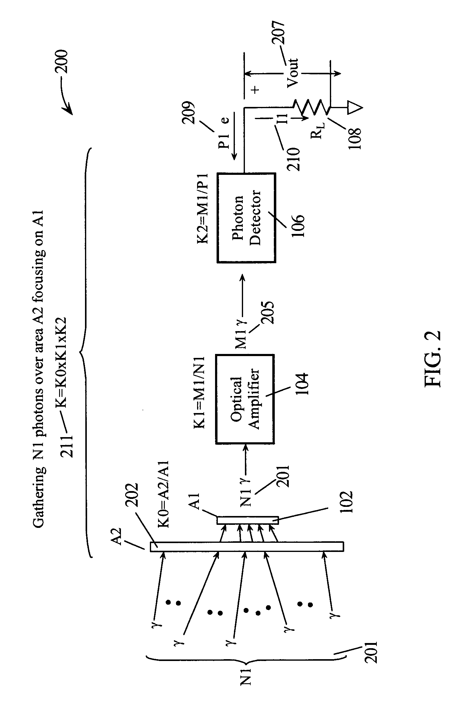
[0028] In other embodiments of the present invention, optical photon gathering elements such as lenses may be employed to increase the numbers of input photons per unit time and to improve overall system performance parameters.

Problems solved by technology

Noise and voltage breakdown problems can arise when detectors are made to operate at their limits.
In some cases, extreme cooling is required.
In other cases, the sensitive detectors can be quite bulky.
These devices, however, only have time resolutions in the microsecond range.
However, a limit on the largeness of the aperture may be set by the acceptance angles in the subsequent optical system.
If a “photon event” comprises emissions from gunfire and chemical explosions (non-nuclear) there is a problem in the detection of radio frequency spectrum.
However, optical frequencies cannot penetrate dense clouds, smoke, or foliage.
But at radio frequencies, antennas are used to capture energy and the antennas suffer from severe limitations.
If an attempt is made to recapture the frequency dependent losses with gain in the antenna, the radiation pattern becomes very directive, requiring prior knowledge of the source location in order to point the antenna, limiting usefulness as a detector.
So lower frequencies provide the required penetration but are problematic to detect because they require antennas.
While many techniques have been employed separately to accomplish photon collection, optical amplification, and photon detection, no single system has incorporated all the necessary elements to achieve a photon detection system that is optimized for sensitivity, size, signal to noise, etc. and yet configured with off the shelf components.

Method used


Image

  • System and method for sensitive photon detection
  • System and method for sensitive photon detection
  • System and method for sensitive photon detection

Examples


Embodiment Construction

[0040] In the following description, numerous specific details are set forth to provide a thorough understanding of the present invention. However, it will be obvious to those skilled in the art that the present invention may be practiced without such specific details. In other instances, well-known circuits may be shown in block diagram form in order not to obscure the present invention in unnecessary detail. For the most part, details concerning timing considerations and the like have been omitted inasmuch as such details are not necessary to obtain a complete understanding of the present invention and are within the skills of persons of ordinary skill in the relevant art.

[0041] Refer now to the drawings wherein depicted elements are not necessarily shown to scale and wherein like or similar elements are designated by the same reference numeral through the several views. In the following components may be referred to as devices, systems or simply by the function name, for example...


PUM


Abstract

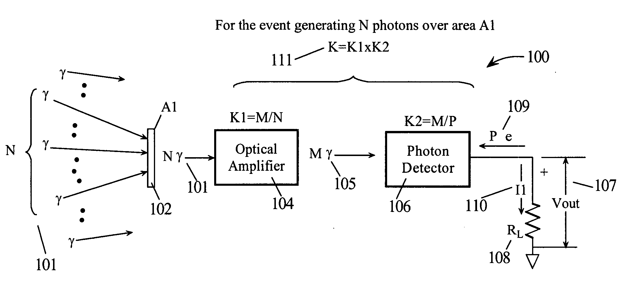
A sensitive photon detection system generates an electronic photon sensor signal as a K factor times a number N photons per unit time. The system is configured by combining a separate optical amplifier with a gain factor K1 with a photo detector with a gain factor K2 such that K may be realized as the product of K1 and K2. The values of K1 and K2 are chosen to meet a predetermined K while optimizing a signal quality of the photon sensor signal. The optical amplifier may be preceded by a photon gathering device and / or a light chopping device to further optimize system performance. Further, the photon sensor signal may be further processed analog circuitry or may be digitized and processed using digital signal processing to generate an enhanced photon sensor signal with enhanced signal quality by adding gain and / or bandwidth limiting.

Description

PRIORITY BENEFIT AND CROSS REFERENCE TO RELATED APPLICATIONS [0001] This application is related to the following commonly owned copending U.S. patent application: [0002] Provisional Application Ser. No. 60 / 665,065, “Sensitive Photon Detector System”, filed Mar. 24, 2005, and claims the benefit of its earlier filing date under 35 U.S.C. § 119(e).TECHNICAL FIELD [0003] The present invention relates in general to systems for detecting the numbers and the energy of particles and in particular to systems for detecting photons. BACKGROUND INFORMATION [0004] Photon detection is widely used in applications as varied as process monitoring, optical communications, spectroscopy, remote sensing, quantum cryptography, and tracking. A simple means for improving the sensitivity of photon detection is desired and would result in an increased range of applications with photon detection systems with improved performance. [0005] There has been much work directed at improving the sensitivity of photon ...

Claims


Application Information

Patent Timeline
Patent Type & Authority Applications(United States)
IPC IPC(8): G01J1/00
CPCG01J1/02G01J1/0295G01J1/04G01J1/42G01J1/044G01J1/0459G01J1/0422
Inventor CERWIN, STEPHEN A.CHANG, DAVID B.
Owner SOUTHWEST RES INST
Learn More