Branched vessel endoluminal device with fenestration

a branching vessel and endoluminal technology, applied in the field of prostheses, can solve the problems of affecting the function of blood vessels and ducts, and sometimes weakening or even tearing, and affecting the flow of blood

Active Publication Date: 2006-11-02
THE CLEVELAND CLINIC FOUND
View PDF7 Cites 130 Cited by
  • Summary
  • Abstract
  • Description
  • Claims
  • Application Information

AI Technical Summary

Benefits of technology

[0026] In yet another aspect of the present invention, there is provided an endoluminal prosthesis, including a prosthetic trunk. The prosthetic trunk comprises a trunk lumen extending therethrough, a wall, and an anastomosis in the wall. A prosthetic branch includes a branch lumen extending therethrough. The branch lumen is in fluid communication with the trunk lumen through the anastomosis. The prosthesis includes a stent. The stent includes a stent perimeter attached to the prosthetic trunk and at least one hoop extending away from the perimeter into the prosthetic branch. The invention also encompasses stent structures which include at least one part formed to accommodate one or more prosthetic branches on the prosthetic trunk. The stents may include a curved or hooped portion.

Problems solved by technology

The functional vessels of human and animal bodies, such as blood vessels and ducts, occasionally weaken or even rupture.
For example, the aortic wall can weaken, resulting in an aneurysm.
Upon further exposure to hemodynamic forces, such an aneurysm can rupture.
If these branch vessels are blocked by the prosthesis, the original blood circulation is impeded, and the patient can suffer.
If, for example, the celiac artery is blocked by the prosthesis, the patient can experience abdominal pain, weight loss, nausea, bloating and loose stools associated with mesenteric ischemia.
The blockage of any branch vessel is usually associated with unpleasant or even life-threatening symptoms.
Furthermore, some aneurysms extend into the branch vessels.
High morbidity and mortality rates are associated with these aneurysms.
Some of these branch extensions and their associated prosthetic branches may dislocate, kink and / or cause poor hemodynamics.
These problems may lead to thrombogenesis and endoleaks at the interconnection of the prosthetic branch and branch extension.

Method used


Image

  • Branched vessel endoluminal device with fenestration
  • Branched vessel endoluminal device with fenestration
  • Branched vessel endoluminal device with fenestration

Examples


example 1

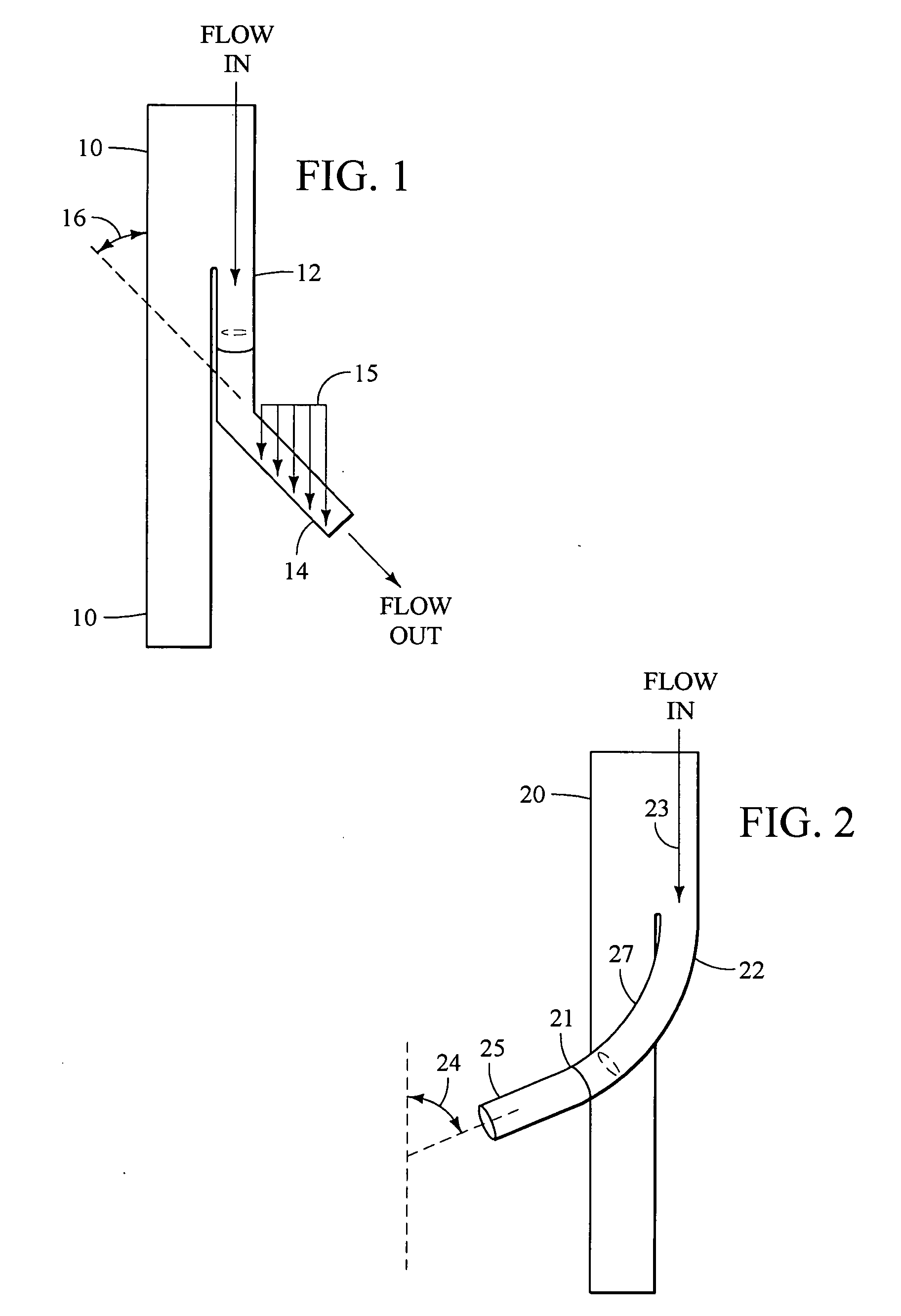
[0225] The flow force on the branched limb is dependent upon the loads applied to the branch point and ultimate angulation of the prosthetic branch. Of particular interest are the forces that may cause separation of the branch extension from the prosthetic branch. Forces due to flow in the y-direction, if significant enough, can become larger than the frictional forces that hold the branch extension and the prosthetic branch together, resulting in separation. If the separation is substantial, a type III endoleak will occur and the aneurysm will no longer be excluded.

[0226] The prostheses described above may be subjected to an in vitro leak pressure test. The purpose of this test procedure is to determine the minimum internal pressure required causing leakage at the mating point between two prostheses.

[0227] The test requires a pressure transducer, a pressure monitor, water / glycerin mixture (dyed) @ 3.64 cP, water bath, submersible heater, water pump, temperature controller, mating...

example 2

[0230] The prostheses described above may be subjected to an in vivo test, preferably in non-human mammals. One animal that is suitable for implantation of the prosthesis for testing and therapeutic purposes is the domestic cow. For testing purposes, six- to ten-week-old male calves were used.

[0231] As presurgical preparation, each animal was given a daily dose of 325 mg of aspirin beginning on the day prior to the procedure for the purpose of platelet inhibition. Each animal was kept without food for approximately 8-12 hours and without water for approximately 2 hours preceding each procedure. A pre-operative baseline ACT was measured in a Hemochron Jr. Signature Series Machine® (available from ITC in Edison, N.J.).

[0232] Each calf was sedated with Xylazine (1.0 mg / 10 lbs, IM). Once the animal was lightly sedated, an induction mask was used to deliver Isofluorane (2-4%). The calf's face was placed into the mask while the inhalation anaesthetic was delivered. The animal may be int...

example 3

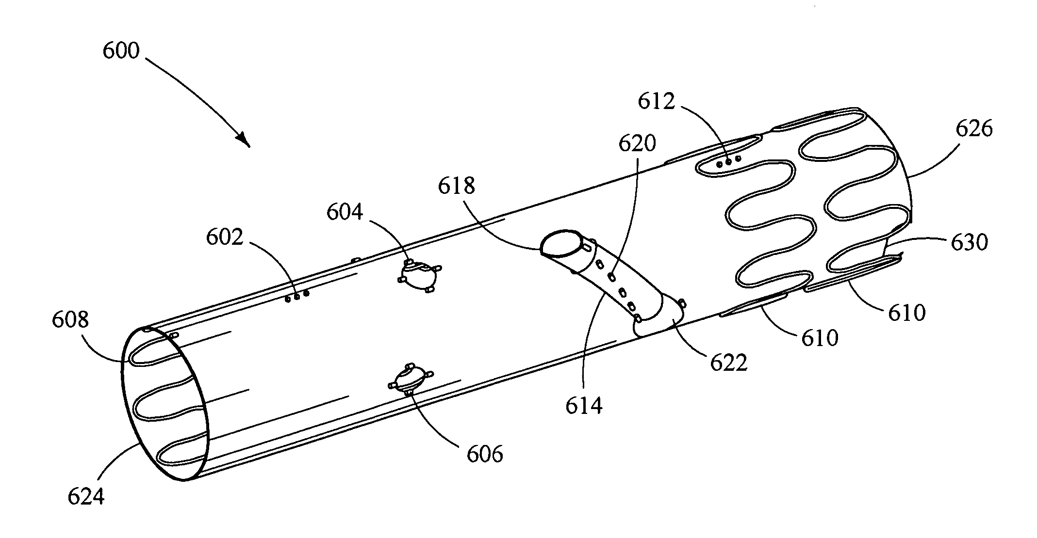
[0240] One helical branch vessel stent graft is deployed such that the branch is properly oriented with respect to the internal iliac artery. Four markers on the distal end of the branch are placed approximately 5 mm above the internal iliac artery. The sheath housing the device is withdrawn to expose the branch limb, leaving the distal end constrained within the sheath in the external iliac artery. The wire dwelling within the contralateral limb is replaced with a steerable guidewire, which is then advanced into the distal aorta and snared with a snare device introduced from the contralateral femoral artery. This provides access from the contralateral groin, through the proximal aspect of the iliac branch, into the iliac limb, and then alongside the outer portion of the distal segment (external iliac artery segment) to the ipsilateral groin.

[0241] Over this through-and-through wire, a 10F or 12F Balkin sheath (Cook Incorporated, Bloomington, Ind.) is introduced and advanced into t...


PUM


Abstract

An endoluminal prosthesis comprises a prosthetic trunk comprising a trunk lumen extending therethrough, a wall, an anastomosis in the wall, and a first fenestration in the wall, wherein the prosthetic trunk has a circumference. The endoluminal prosthesis further comprises a prosthetic branch comprising a branch lumen extending therethrough. The branch lumen is in fluid communication with the trunk lumen through the anastomosis. The prosthetic branch is disposed longitudinally along and circumferentially about the prosthetic trunk.

Description

RELATED APPLICATIONS [0001] This present patent document is a continuation-in-part of U.S. patent application Ser. No. 10 / 756,803, filed Jan. 13, 2004 (U.S. Patent Application Publication No. 2006 / 0058864), which claims the benefit of the filing date under 35 U.S.C. §119(e) of U.S. Provisional Patent Application Ser. No. 60 / 439,923, filed Jan. 14, 2003; U.S. Provisional Patent Application Ser. No. 60 / 478,107, filed Jun. 11, 2003; and U.S. Provisional Patent Application Ser. No. 60 / 510,636, filed Oct. 10, 2003, all of which are incorporated herein by reference. [0002] This present patent document also claims the benefit of the filing date under 35 U.S.C. §119(e) of U.S. Provisional Patent Application Ser. No. 60 / 671,410, filed Apr. 13, 2005, which is incorporated herein by reference.TECHNICAL FIELD [0003] This invention relates to prostheses for implantation within the human or animal body for the repair of damaged vessels, ducts or other physiological passageways. BACKGROUND [0004] ...

Claims


Application Information

Patent Timeline
Patent Type & Authority Applications(United States)
IPC IPC(8): A61F2/82A61F2/06
CPCA61F2/07A61F2002/061A61F2002/065A61F2/89A61F2002/068A61F2002/075A61F2250/0063A61F2002/067
Inventor GREENBERG, ROY K.WEST, KARL J.SKENDER, DAVORIN K.FOSTER, JAMES C.
Owner THE CLEVELAND CLINIC FOUND
Why Eureka
Try Eureka