Apparatus and method of abnormality diagnosis for supercharging pressure control system

a control system and abnormal diagnosis technology, applied in the direction of electric control, machines/engines, combustion engines, etc., can solve the problems of deterioration in the controllability of the supercharging pressure control, deterioration of linearity, and possible deterioration of the changing characteristic of the actual supercharging pressure to the change of the wgv control signal

Inactive Publication Date: 2006-11-09
DENSO CORP
View PDF14 Cites 66 Cited by
  • Summary
  • Abstract
  • Description
  • Claims
  • Application Information

AI Technical Summary

Benefits of technology

[0015] If the abnormality occurs in the bypass valve, the bypass valve cannot be opened regardless of the satisfaction of the operating condition (output of the valve opening command in a case of the electrically driven bypass valve). In this case, when the bypass valve is normally opened, the throttle-upstream-pressure changes (reduces) caused by it. However, upon occurrence of the abnormality in the bypass valve, the fluctuation in the throttle-

Problems solved by technology

However, in a supercharging pressure control system where a foreign object such as oil adheres inside the electromagnetic valve for driving the WGV, a changing characteristic of the actual supercharging pressure to the change in the WGV control signal varies in a partial region, so that a linearity in the changing characteristic of the actual supercharging pressure to the change in the WGV control signal possibly deteriorates.
Occurrence of such an abnormality possibly causes deterioration in controllability of the supercharging pressure control.
However, since the changing characteristic of the actual supercharging pressure to the change in the

Method used


Image

  • Apparatus and method of abnormality diagnosis for supercharging pressure control system
  • Apparatus and method of abnormality diagnosis for supercharging pressure control system
  • Apparatus and method of abnormality diagnosis for supercharging pressure control system

Examples


first embodiment

[0033] An abnormality diagnosis apparatus for a supercharging pressure control system in a first embodiment of the present invention will be hereinafter explained with reference to the accompanying drawings.

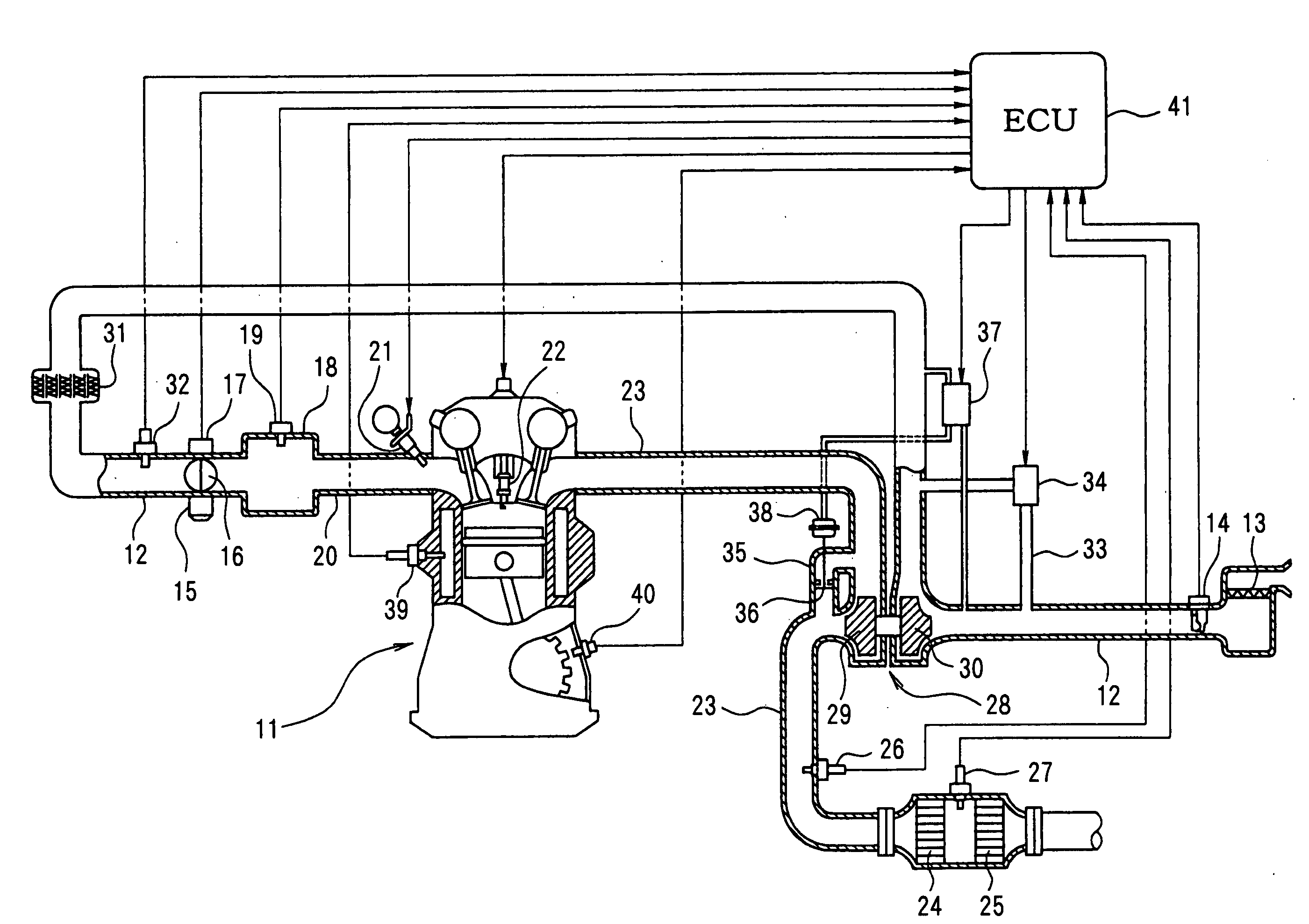
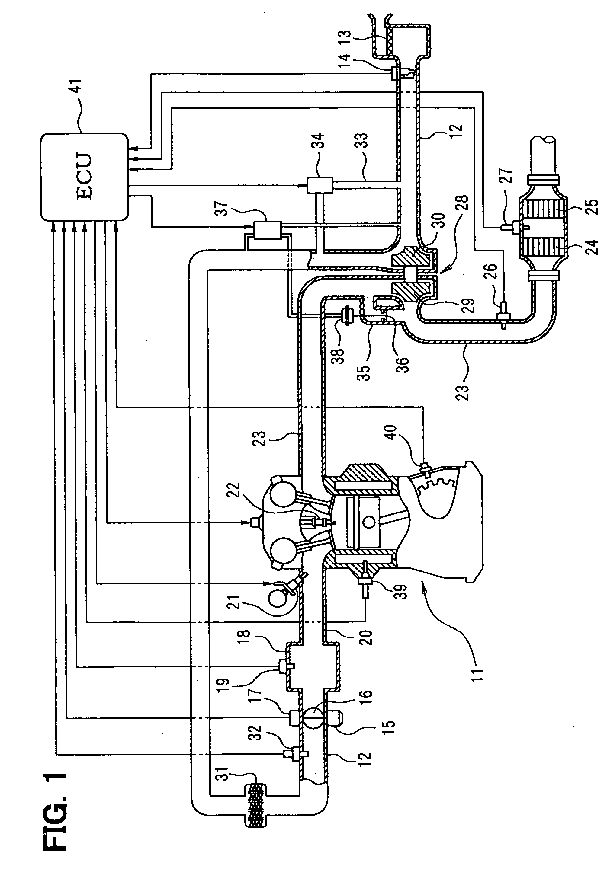
[0034] First, a schematic construction of an entire engine control system will be explained with reference to FIG. 1. An air cleaner 13 is located in the most upstream section of an intake pipe 12 (intake passage) for an engine 11 as an internal combustion engine. An air flow meter 14 for detecting an intake air quantity is located in the intake pipe 12 at the downstream side of the air cleaner 13. A compressor 30 in a supercharger of an exhaust driven type to be described later and an intercooler 31 for cooling intake air pressurized by the compressor 30 are provided in the take pipe 12 at the downstream side of the air flow meter 14. A supercharging pressure sensor 32 for detecting an intake pressure (hereinafter referred to as supercharging pressure) in the intake pipe 12 at ...

second embodiment

[0086] A schematic construction diagram of an entire engine control system will be explained with reference to FIG. 9.

[0087] In an engine 110 shown in FIG. 9, a throttle valve 114 as air quantity adjusting means is located in an intake pipe 111 and an opening of the throttle valve 114 is adjusted by a throttle actuator 115 such as a DC motor. A throttle opening sensor for detecting an opening of the throttle valve 114 (throttle opening) is housed in the throttle actuator 115. A supercharging pressure sensor 112 and an intake temperature sensor 113 are located at an upstream side of the throttle valve 114. The supercharging pressure sensor 112 detects a pressure (a supercharging pressure by a turbocharger to be described later) at the upstream side of the throttle valve 114. The intake temperature sensor 113 detects an intake temperature at the upstream side of the throttle valve 114.

[0088] A surge tank 116 is located downstream of the throttle valve 114 and an intake pressure sens...

third embodiment

[0116] In the second embodiment, after the throttle valve 114 is fully closed, the pressure determination value Pth1 is set according to the changing pattern of the throttle-upstream-pressure caused by the opening of the air bypass valve 135 and also at a state when the throttle-upstream-pressure is more than the pressure determination value Pth1, an abnormality determination of the air bypass valve 135 is made based upon continuation time of this state. However, in the third embodiment, the above abnormality determination method is altered. That is, differences in pressure between the throttle-upstream-pressure Pb and the pressure determination value Pth1 are integrated to execute an abnormality determination of the air bypass valve 135 based upon an integration value of the pressure differences.

[0117] As for a calculation process of the ECU 150, the process of steps 1106 to 1110 in FIG. 10 is altered into the process shown in FIG. 13. That is, in FIG. 13, at step 1201, it is dete...


PUM


Abstract

An opening of a waste gate vale is adjusted to control an actual supercharging pressure of intake air. Abnormality in a changing characteristic of the actual supercharging pressure relative to a change in a TCV control duty value can be detected. When an engine is in a steady operation condition, the TCV control duty value is forcibly changed repeatedly by a predetermined amount from 0% to 100%. A deviation between a target supercharging pressure corresponding to the TCV control duty value and an actual supercharging pressure is calculated each time the TCV control duty value is changed by the predetermined amount. This deviation is compared with an abnormality determination value to determine presence/absence of the abnormality in the changing characteristic of the actual supercharging pressure relative to the change in the TCV control duty value.

Description

CROSS-REFERENCE TO RELATED APPLICATION [0001] This application is based on Japanese Patent Applications No. 2005-194963 filed on Jul. 4, 2005, and No. 2005-267865 filed on Sep. 15, 2005, the disclosure of which are incorporated herein by reference. FIELD OF THE INVENTION [0002] The present invention relates to an apparatus and a method of an abnormality diagnosis for a supercharging pressure control system which controls a supercharging pressure of intake air supercharged by a supercharger. BACKGROUND INFORMATION [0003] There is known an in-vehicle internal combustion engine provided with a supercharger of an exhaust turbine driven type (i.e., turbocharger), aiming at high power output of the engine or the like. [0004] JP-2000-345852A discloses a system which controls a supercharging pressure of intake air supercharged by this supercharger. This system is so structured that a waste gate valve (WGV) is located in an exhaust bypass passage bypassing an exhaust turbine to feedback-cont...

Claims


Application Information

Patent Timeline
IPC IPC(8): F02D23/00F02B33/44
CPCF02B29/04F02B37/18Y02T10/144F02D41/221F02B39/16Y02T10/12
Inventor SAGISAKA, YASUOMUKAI, YASUOYAMAGUCHI, MASAHIKOUEDA, KUNIAKI
Owner DENSO CORP
Why Eureka
Try Eureka