Artificial human limbs and joints employing actuators, springs, and variable-damper elements

Inactive Publication Date: 2006-11-09
MASSACHUSETTS INST OF TECH
View PDF0 Cites 406 Cited by
  • Summary
  • Abstract
  • Description
  • Claims
  • Application Information

AI Technical Summary

Benefits of technology

[0041] In the construction of a biologically realistic limb system that is high performance, light weight, quiet and energetically efficient, embodiments of the invention to be described below employ passive-elastic, variable-damping, and motor elements. Since it is desirable to minimize the

Problems solved by technology

None of these systems are able to add energy during the stride to help keep the body moving forward or to reduce impact losses at heel strike.
However, for most applications, the SEA requires a tremendous amount of electric power for its operatio

Method used


Image

  • Artificial human limbs and joints employing actuators, springs, and variable-damper elements
  • Artificial human limbs and joints employing actuators, springs, and variable-damper elements
  • Artificial human limbs and joints employing actuators, springs, and variable-damper elements

Examples


embodiment 1

[0121] Mechanical Design

[0122] Embodiment 1 is depicted in FIGS. 12-14. As seen in the lumped parameter model of FIG. 12, the first embodiment implements an artificial ankle and comprises a motor 1201 and a global variable damper 1203 to provide control of joint position and mechanical energy absorption rate. In the description that follows, it will be shown how this first embodiment may be used to implement an artificial ankle, with a global one way spring 1205 being placed in parallel with the motor 1201 and the global variable damper 1203 between the parent link 1210 at the shin and a child link 1212 at the foot.

[0123] As seen in the schematic diagram of FIG. 13, the first embodiment forms a joint 1300 between the parent link seen 1301 (at the shin shown at 1210 in FIGS. 12 and 1402 in FIG. 14) and a child link 1303 (at the foot link seen at 1212 in FIG. 12 and at 1408 in FIG. 14). An electric motor seen at 1305 (and at 1201 in FIGS. 12 and 1401 in FIG. 14) rotates the foot mem...

embodiment 2

[0129] Mechanical Design

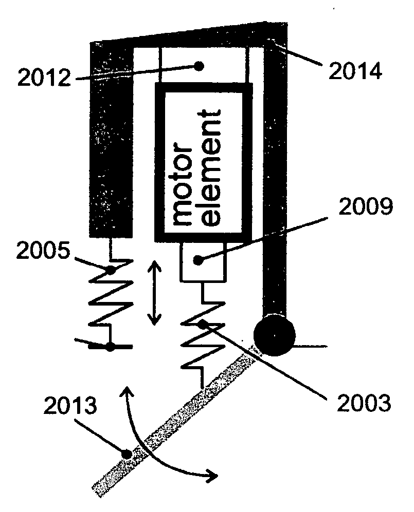
[0130] Embodiment 2 is shown in FIGS. 15-18. As seen by a comparison of the lumped parameter models seen in FIGS. 12 and 15, and also comparing the schematic drawings of FIGS. 13 and 16, it may be seen that the second embodiment includes an additional “motor series spring” element seen at 1501 in FIG. 1, at 1601 in FIG. 16, and at 1701 in FIGS. 17 and 18. In addition to the capabilities offered by Embodiment 1, Embodiment 2 provides for the control of hybrid actuator force by an active spring deflection control by the motor and an active damping control by the variable damper. In addition, Embodiment 2 includes the capacity to act as a catapult where a spring is slowly compressed and that stored potential energy is used all at once at a later time. For the catapult control, the global variable-damper 1605 will be able to control the damping of the joint in order to modulate how much energy is actually released from the stored catapult energy. In the section ...

embodiment 3

[0136] Mechanical Design

[0137] Embodiment 3 is shown in FIGS. 19-21 and also comprises a motor, a motor series spring, and a variable damper in parallel with the motor as seen in FIG. 19. The third embodiment differs from the second in that the variable damper is connected to retard motor motion. In addition to the capabilities offered by Embodiment 1, Embodiment 3 provides for low-power spring stiffness and spring equilibrium point control.


PUM


Abstract

Biomimetic Hybrid Actuators employed in biologically-inspired musculoskeletal architectures employ an electric motor for supplying positive energy to and storing negative energy from an artificial joint or limb, as well as elastic elements such as springs, and controllable variable damper components, for passively storing and releasing energy and providing adaptive stiffness to accommodate level ground walking as well as movement on stairs and surfaces having different slopes.

Description

CROSS REFERENCE TO RELATED APPLICATIONS [0001] This application claims the benefit of the filing date of U.S. Provisional Patent Application Ser. No. 60 / 666,876 filed on Mar. 31, 2005 and further claims the benefit of the filing date of U.S. Provisional Patent Application Ser. No. 60 / 704,517 filed on Aug. 1, 2005. The disclosures of both of the foregoing provisional applications are incorporated herein by reference.FIELD OF THE INVENTION [0002] This invention relates generally to prosthetic devices and artificial limb systems, including robotic, orthotic, exoskeletal limbs, and more particularly, although in its broader aspects not exclusively, to artificial ankle, knee, and hip joints. BACKGROUND OF THE INVENTION [0003] In the course of the following description, reference will be made to the papers, patents and publications presented in a list of references at the conclusion of this specification. When cited, each listed reference will be identified by a numeral within curly-brace...

Claims


Application Information

Patent Timeline
IPC IPC(8): B62D51/06A61F2/64
CPCA61F2/60B62D57/032A61F2/64A61F2/6607A61F2/68A61F2002/5004A61F2002/503A61F2002/5033A61F2002/5075A61F2002/6818A61F2002/701A61F2002/704A61F2002/7625A61F2002/7635A61F2002/764A61F2002/7645B25J19/0008A61F2/605A61F2/604A61F2/70A61F2002/5072
Inventor HERR, HUGH M.PALUSKA, DANIEL JOSEPHDILWORTH, PETER
Owner MASSACHUSETTS INST OF TECH
Why Eureka
Try Eureka