Power supply regulator circuit and semiconductor device

a technology of power supply regulator and semiconductor device, which is applied in the direction of electric variable regulation, process and machine control, instruments, etc., can solve the problems of overcurrent detection delay time td, difficult to reduce the input voltage dependence of peak value, and move overload detection to the heavy load side, so as to reduce the change of output current and prefer the effect of constant current drooping characteristi

Inactive Publication Date: 2006-11-09
COLLABO INNOVATIONS INC
View PDF4 Cites 12 Cited by
  • Summary
  • Abstract
  • Description
  • Claims
  • Application Information

AI Technical Summary

Benefits of technology

[0036] In consideration of the problem, it is an object of the present invention to provide a power supply regulation circuit which makes it possible to eliminate the need for a constant current control circuit, a photocoupler, and a resistor for detecting output current, reduce a change of output current changing with input voltage in a constant current region, and achieve a preferable constant current drooping characteristic.

Problems solved by technology

This means that overload detection moves to the heavy load side.
However, in the case where the on time Ton is short relative to the overcurrent detection delay time Td, that is, “Td / Ton” is large, it is difficult to reduce the input voltage dependence of the peak value Ip of the drain current ID passing through the switching element.
Thus the long overcurrent detection delay time Td and the short on time Ton are disadvantageous to a reduction of the input voltage dependence of the peak value Ip of the drain current ID.
Thus in the conventional switching power supply, it is quite difficult to make the output current IO constant relative to a change of the input voltage VIN and a load.

Method used


Image

  • Power supply regulator circuit and semiconductor device
  • Power supply regulator circuit and semiconductor device
  • Power supply regulator circuit and semiconductor device

Examples


Embodiment Construction

[0089] The following will describe a power supply regulation circuit according to an embodiment of the present invention with reference to the accompanying drawings. The power supply regulation circuit is a switching power supply in the present embodiment.

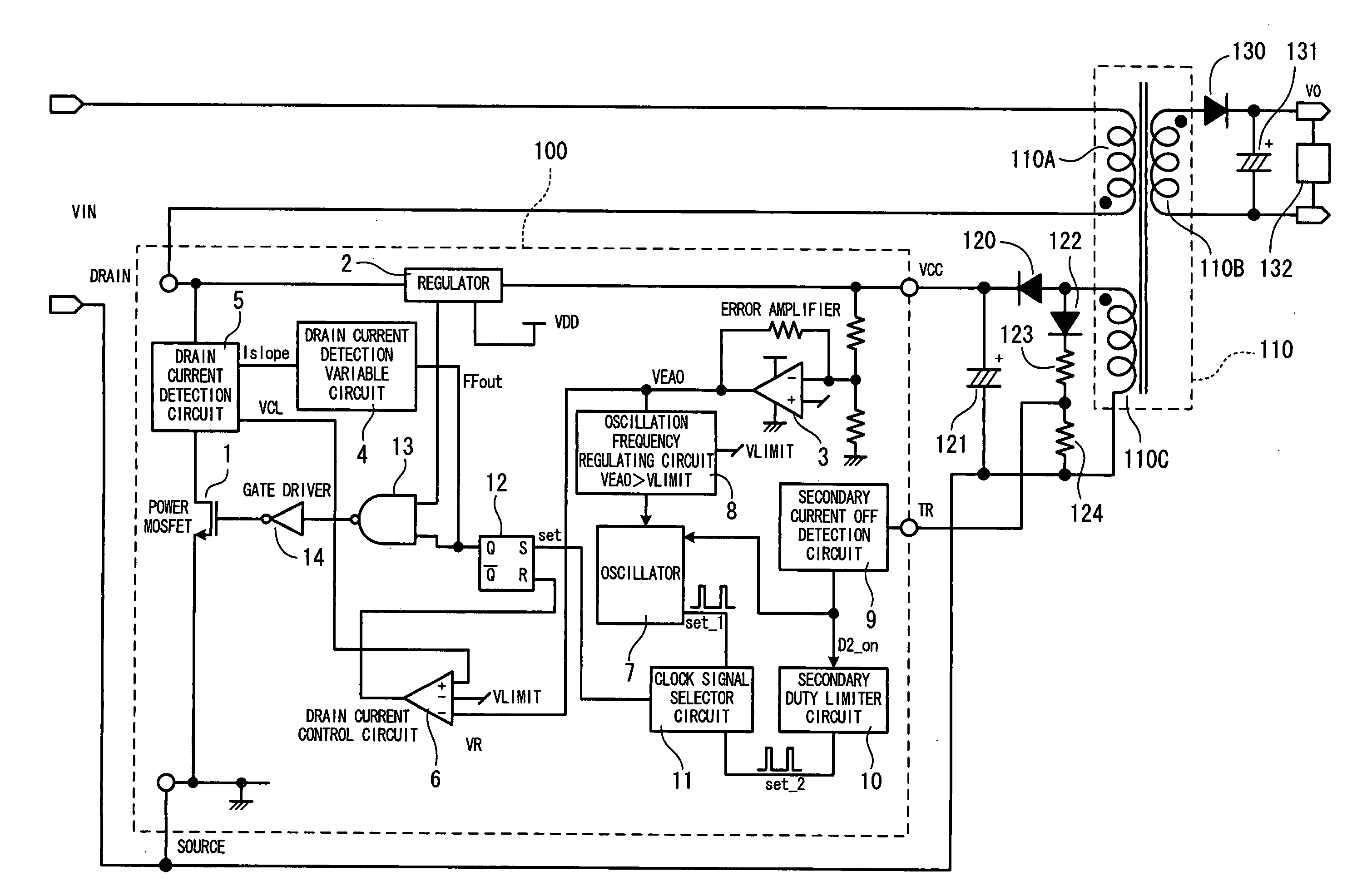
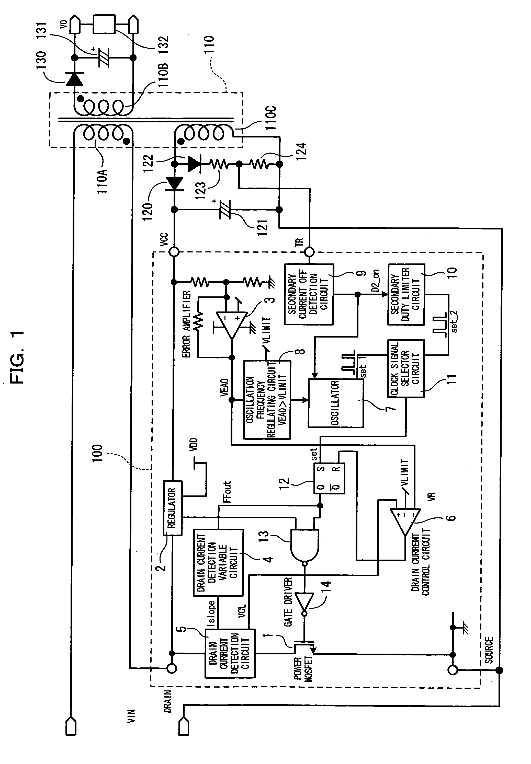
[0090]FIG. 1 is a block diagram showing a structural example of the switching power supply according to the present embodiment.

[0091] In FIG. 1, a switching element 1 is a power MOSFET which has three terminals of DRAIN terminal acting as an input terminal (first terminal), SOURCE terminal acting as an output terminal (second terminal), and GATE terminal acting as a control terminal. The switching element 1, in response to a control signal received on the control terminal, oscillates so as to electrically couple or decouple the input terminal and the output terminal. Further, the switching element 1 controls, according to the oscillating operation, the on / off of current passing through a primary winding 110A of a transformer 110....


PUM


Abstract

A power supply regulation circuit is provided which can achieve a preferable constant current drooping characteristic without the need for a constant current control circuit on the secondary side. During a constant current operation, a switching element (1) is turned on so as to keep constant the on duty of secondary current passing through a secondary winding (110B) of a transformer (110), so that a constant current drooping characteristic is achieved. Further, at this moment, a current limit dictating the maximum value of drain current (ID) passing through the switching element (1) is changed between first and second levels during the on time of the switching element such that the drain current (ID) has a constant peak value.

Description

FIELD OF THE INVENTION [0001] The present invention relates to a power supply regulation circuit and a semiconductor device which have a constant current drooping characteristic as an output characteristic. BACKGROUND OF THE INVENTION [0002] Conventionally, switching power supplies have been widely available as a power supply regulation circuit for a charger, each of which achieves a constant current drooping characteristic by means of a constant current control circuit provided on the secondary side. The switching power supply comprises, on the secondary side, a resistor for detecting an output current, a constant current control circuit for controlling current passing through the resistor to a constant level, and a photocoupler for transmitting the signal of the constant current control circuit to the primary side. When the output current is equal to or higher than a fixed value, the constant current control circuit is operated. According to the switching power supply having such ...

Claims


Application Information

Patent Timeline
Patent Type & Authority Applications(United States)
IPC IPC(8): H02M3/335
CPCH02M3/33523
Inventor MURATA, KAZUHIROMORI, YOSHIHIRO
Owner COLLABO INNOVATIONS INC
Why Eureka
Try Eureka