System

a computer-based design and system technology, applied in the field of computer-based design systems, can solve the problems of high cost and time, inefficient and cumbersome conventional approach to engineering design and development effort, and designers often generate designs without reliable estimates of the cost or time required to manufacture a component, and provide a good indication of the cost associated with high volume manufacturing. , to achieve the effect of reducing the pri

Active Publication Date: 2006-11-09
IDEA LAB SRL
View PDF16 Cites 101 Cited by
  • Summary
  • Abstract
  • Description
  • Claims
  • Application Information

AI Technical Summary

Benefits of technology

[0006] Computer-based systems that are configured to provide automated cost estimation address many of the disadvantages of the conventional approach to locating and negotiating with a qualified manufacturer. However, such systems still suffer from significant disadvantage. For example, when generalized manufacturing rules are applied to the cost factors that are extracted from the design information, it is not possible to account for manufacturer-specific variances and capabilities. For example, such a configuration will result in inaccurate estimates if a particular manufactur

Problems solved by technology

The conventional approach to an engineering design and development effort tends to be inefficient, costly and cumbersome in many respects.
For example, the input that designers receive from manufacturers during the design process is generally limited to information relating to particular manufacturing capabilities, and therefore designers often generate designs without the benefit of reliable estimates of the cost or time required to manufacture a component.
While prototype machine shops are helpful in the process of finalizing a component design, they can be expensive, and generally may not provide a good indication of costs associated with high volume manufacturing.
Even when a design is completed, the process of finding a qualified manufacturer typically involves an inefficient process of identifying potential candidates through word-o

Method used


Image

  • System
  • System
  • System

Examples


Embodiment Construction

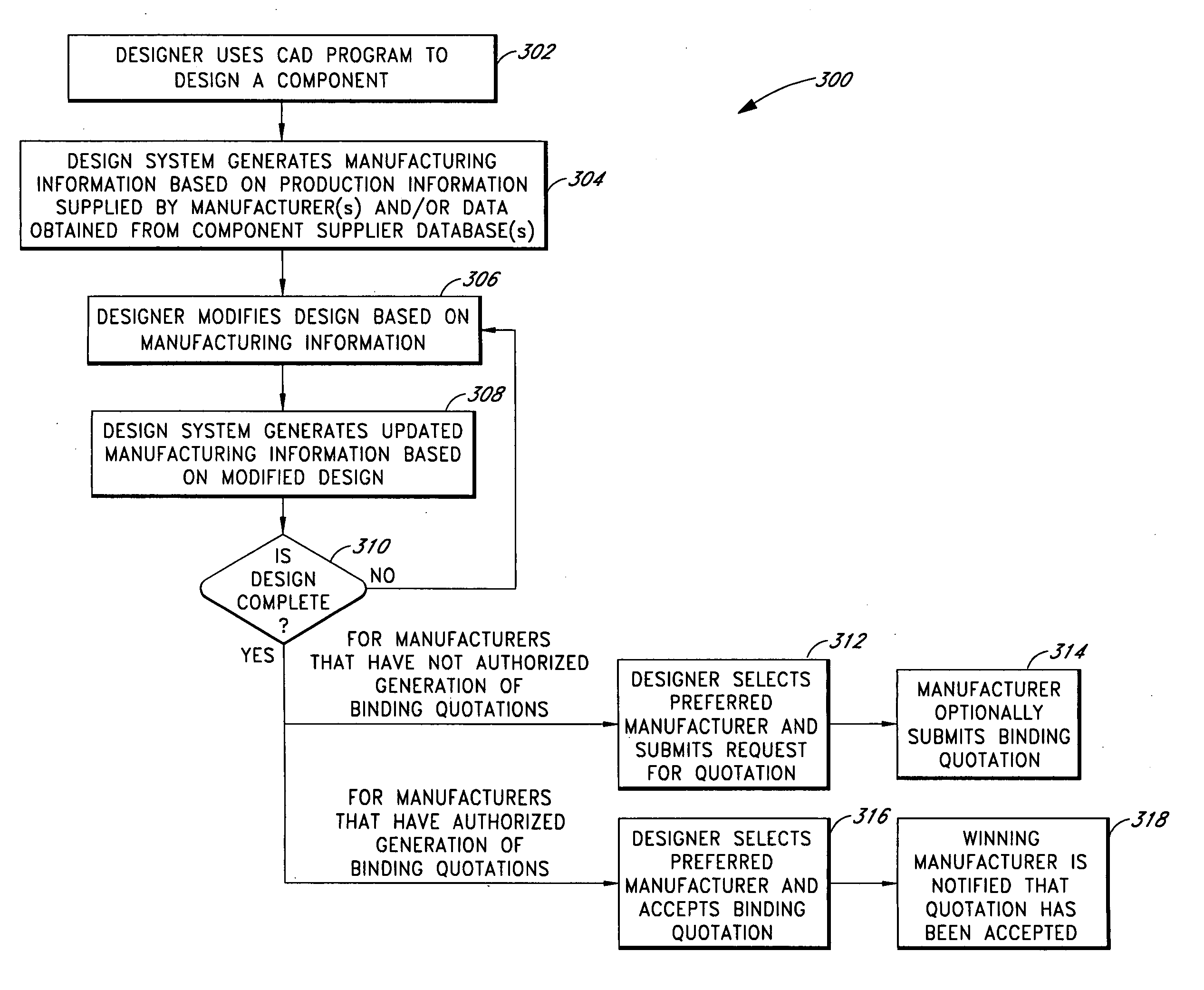
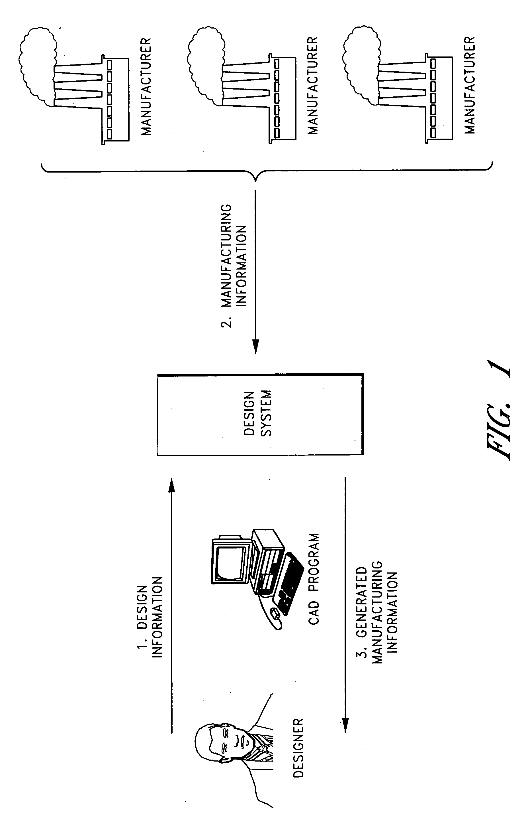
[0027] Disclosed herein are several embodiments of an improved design system. Certain of the disclosed embodiments are intended to allow designers to more efficiently obtain accurate information from multiple manufacturers, suppliers, assemblers, builders, processors, vendors and other purveyors of goods and / or services (collectively referred to herein as “manufacturers”). This allows the product development cycle to be accelerated, thereby advantageously reducing product development costs for designers, and reducing factory idle time and administrative costs for manufacturers. FIG. 1 schematically illustrates how an example design system facilitates communications and transactions between a designer and manufacturers.

[0028] Certain embodiments of the improved design system disclosed herein are configured to interface with and be accessed using a CAD program, as illustrated in FIG. 1. As used herein, the term “CAD program” refers generally to a computer program that is used to assi...


PUM


Abstract

A design system is accessible to a designer and a plurality of manufacturers. The design system comprises a first user interface configured to receive design information for a component from the designer. The design system further comprises a second user interface configured to receive manufacturing information from the plurality of manufacturers. The manufacturing information comprises at least process cost information. The design system further comprises a database comprising the manufacturing information associated with each of the plurality of manufacturers. The design system further comprises a cost estimation module. The cost estimation module is configured to generate a cost estimate for producing the component for each of the plurality of manufacturers. The cost estimate is at least partially based on the process cost information. The cost estimation module is further configured to output the cost estimate for one or more of the plurality of manufacturers to the first user interface.

Description

CROSS-REFERENCE TO RELATED APPLICATIONS [0001] This application claims the benefit of U.S. Provisional Patent Application 60 / 653,552 (filed 16 Feb. 2005), the entire disclosure of which is hereby incorporated by reference herein.FIELD OF THE INVENTION [0002] The present invention relates generally to computer-based design systems, and relates more specifically to computer-based design systems that are capable of using dynamically updated information to facilitate the design process. BACKGROUND OF THE INVENTION [0003] The conventional approach to an engineering design and development effort tends to be inefficient, costly and cumbersome in many respects. For example, the input that designers receive from manufacturers during the design process is generally limited to information relating to particular manufacturing capabilities, and therefore designers often generate designs without the benefit of reliable estimates of the cost or time required to manufacture a component. While proto...

Claims


Application Information

Patent Timeline
IPC IPC(8): G06F19/00
CPCG06F17/50G06Q10/06G06Q50/04G06Q30/0283G06Q30/0601G06Q30/02G06F30/00Y02P90/30
Inventor GROSS, WILLIAM
Owner IDEA LAB SRL
Why Eureka
Try Eureka