Storage system having virtualized resource

a storage system and resource technology, applied in the field of controlling a storage system and a storage subsystem, can solve the problems of host computer not being able to use a function of a storage subsystem in a unified and associated manner for a virtual volume, and cannot achieve an association of functions between storage subsystems, so as to reduce the load of processing on the host computer, reduce processing time, and facilitate management

Inactive Publication Date: 2006-11-09
HITACHI LTD
View PDF47 Cites 69 Cited by
  • Summary
  • Abstract
  • Description
  • Claims
  • Application Information

AI Technical Summary

Benefits of technology

[0015] When a host computer uses a plurality of storage areas and a plurality of logical volumes, integrally controlling the plurality of storage areas and the plurality of logical volumes, so that each control is associated with the other, such a configuration enables advanced system operation and management, leading to a reduction in time required for processing,

Problems solved by technology

However, the conventional control method, and the management method, in which a function of a storage subsystem is individually controlled using software (management software) on the host computer and a management server, cannot achieve an association of functions between storage subsystems.
In particular, if there is a difference in variety of functions (i.e., if kinds of functions included in a storage subsystem are different from those included in the other storage subsystems) and if specifications of a function are different even if a kind of the function is the same as, or similar to, that in the other storage systems, and if a certain storage subsystem does not have a speci

Method used


Image

  • Storage system having virtualized resource
  • Storage system having virtualized resource
  • Storage system having virtualized resource

Examples


Embodiment Construction

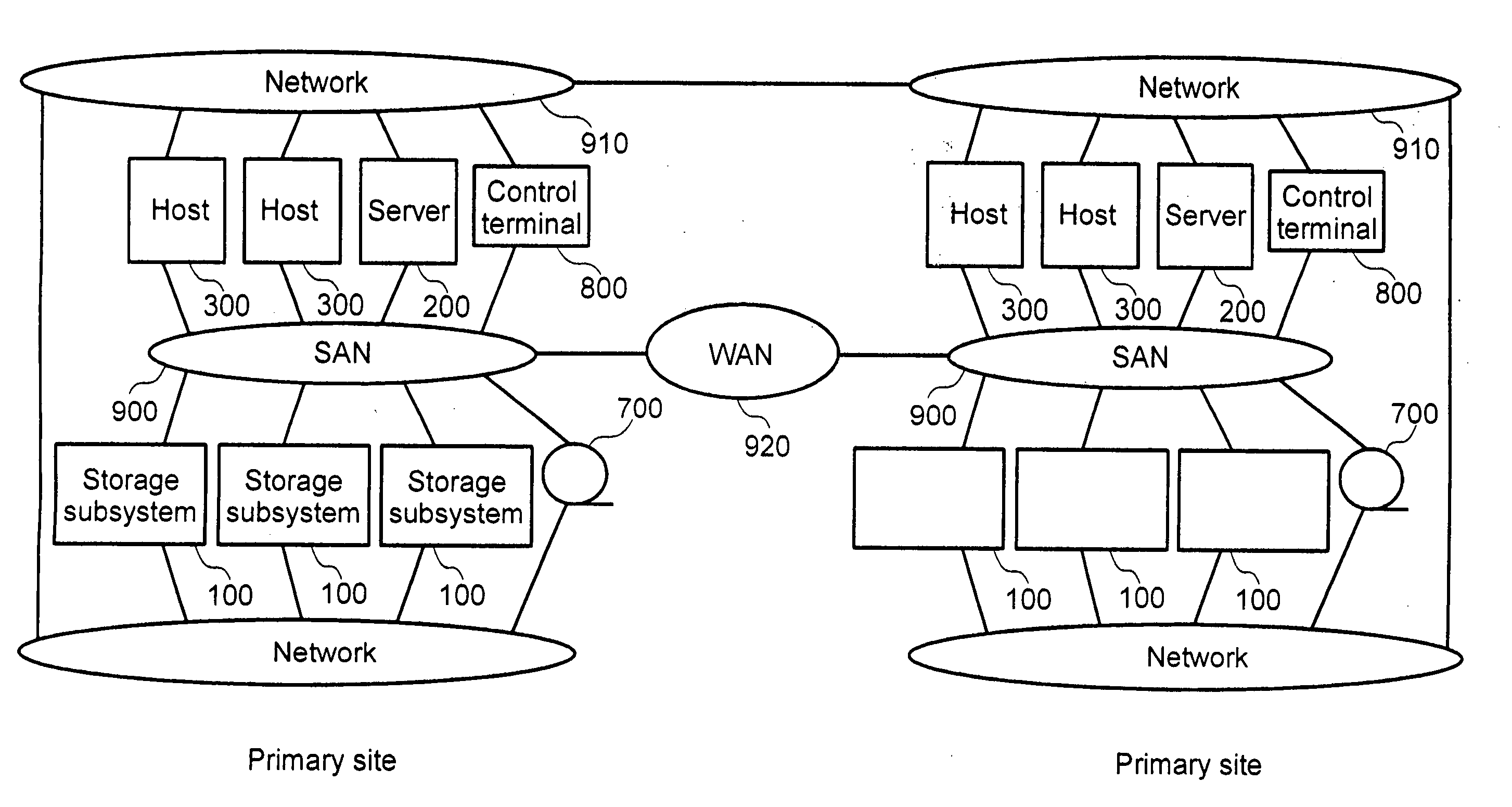
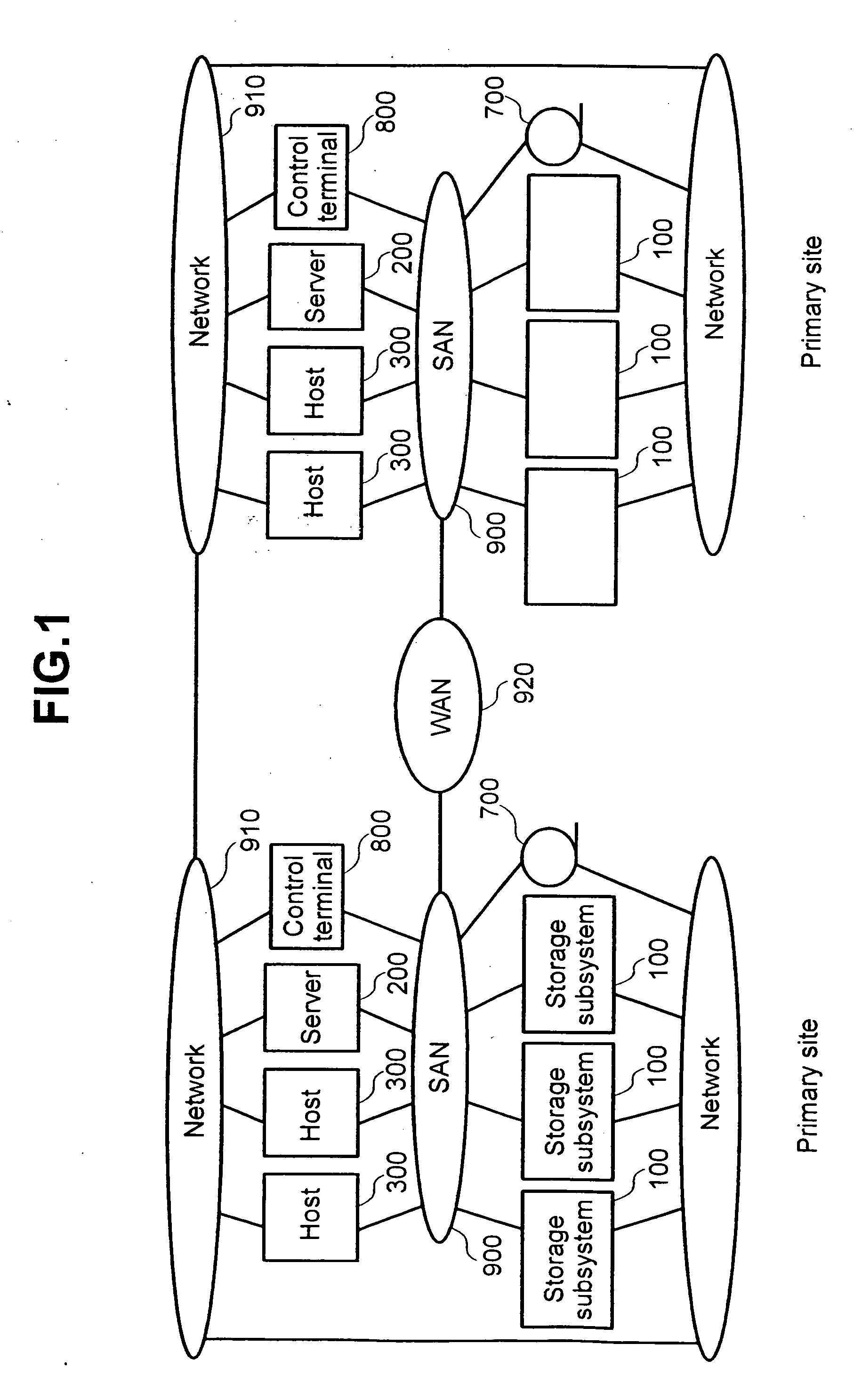
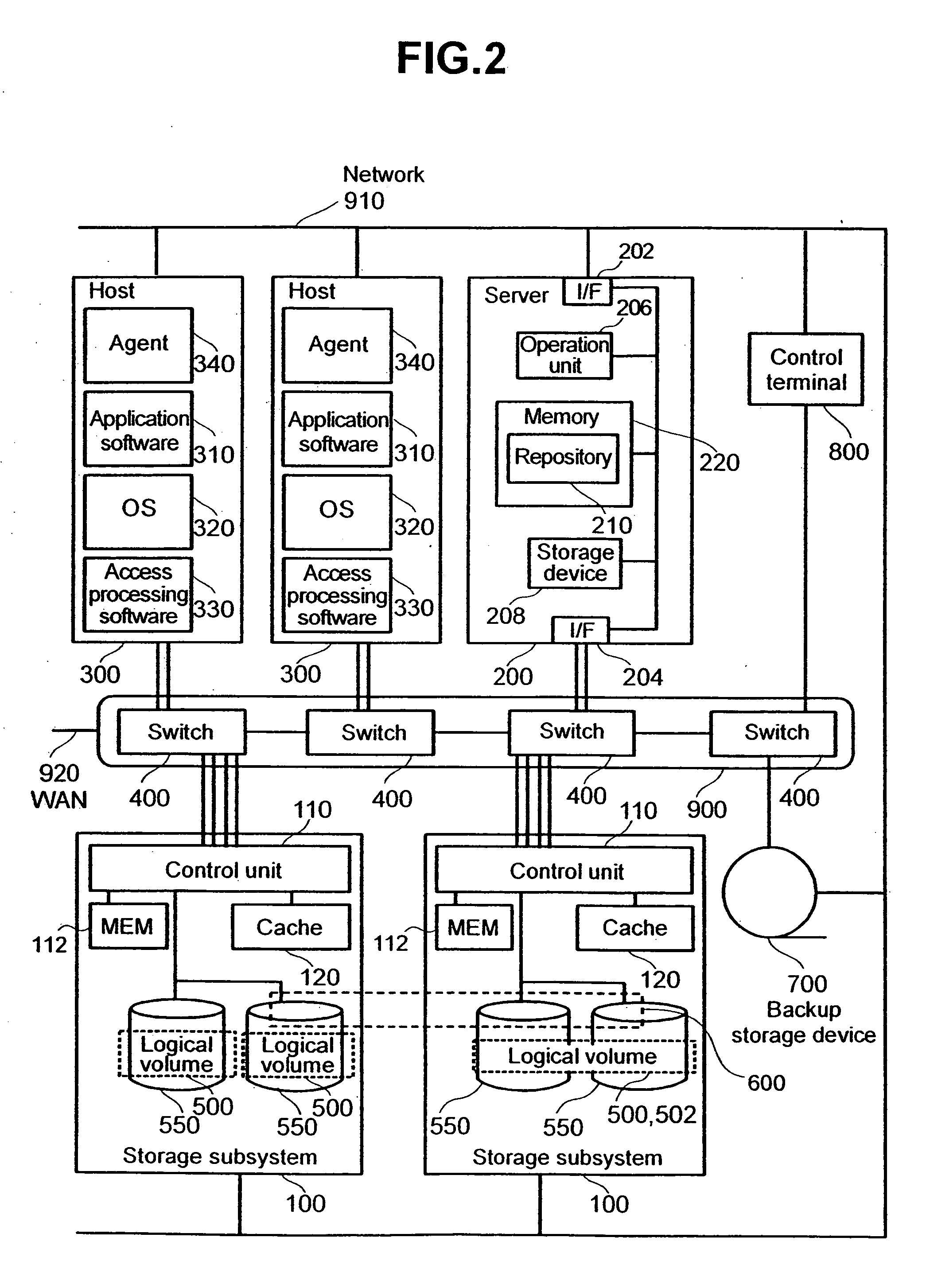
[0041]FIG. 1 is a schematic diagram illustrating a configuration of a storage system according to an embodiment of the present invention. The storage system comprises a primary site and a secondary site, which are connected to each other via a WAN (Wide Area Network) 920.

[0042] Each site comprises one or more host computers (hereinafter referred to as host) 300, one or more computers (hereinafter referred to as server) 200, one or more control terminal 800, one or more backup storage device 700, and a one or more storage subsystems 100, which are mutually connected via a SAN (Storage Area Network) 900 comprising a switch 400 and a hub. Examples of a protocol and standards, which are used in the SAN 900, include, for example, Fiber Channel (FC), IP, Infini, and Band. The SAN 900, which is configured according to FC, will be described as an example in the following description.

[0043] The host 300, the server 200, and the storage subsystem 100 are also mutually connected via a networ...


PUM


Abstract

A storage system configured to provide a storage area to a host coupled to the storage system includes a first storage device of first type being configured to store data and provide one or more data-storage-related functions. A second storage device of second type is configured to store data and provide one or more data-storage-related functions. A virtual volume provides a storage location and being associated with at least one of the first and second storage devices. A database includes information relating to the one or more data-storage-related functions that the first and second storage devices are configured to perform. A first server is coupled to the first and second storage devices and having access to the database, the first server being configured to access the database in response to a data-storage-related-function request from the host involving at least one of the first and second storage devices. The database is accessed to determine whether or not the at least one of the first and second storage devices is capable of performing the request from the host. The first server further being configured to perform the request if the determination is negative or provide an instruction to the at least one of the first and second storage devices to perform to the request if the determination is positive.

Description

CROSS-REFERENCES TO RELATED APPLICATIONS [0001] The present application is related to and claims priority from Japanese Patent Application No. 2002-125168, filed on Apr. 26, 2002. BACKGROUND OF THE INVENTION [0002] The present invention relates to a method for controlling a storage system and storage subsystem, and more particularly to a method for controlling a storage system that virtualizes a resource and apparatus thereof. [0003] In an information processing system, there is a possibility that processing in a computer is aborted by a program bug executed in the computer, or the like, causing data included in the information processing system to be in a state of contradiction. In addition, data managed by the information processing system may be erased by human error. [0004] In order to reliably restore the data of the information processing system, which is in such a state, the information processing system generally obtains a backup of the data on a routine basis. Japanese Pate...

Claims


Application Information

Patent Timeline
IPC IPC(8): G06F15/16G06F3/06G06F11/14G06F11/20G06F12/00G06F15/00G06F15/173G06F17/30H04L29/08
CPCG06F11/1456Y10S707/99953G06F2201/80G06F3/0605G06F3/0629G06F3/0659G06F3/0665G06F3/067G06F11/1458G06F11/1466G06F11/2064G06F11/2082G06F17/30067G06F21/80G06F2201/84H04L67/1095H04L67/1097Y10S707/99939G06F11/1464G06F16/10
Inventor ARAKAWA, HIROSHIOEDA, TAKASHIMATSUNAMI, NAOTOITO, RYUSUKE
Owner HITACHI LTD
Why Eureka
Try Eureka