Exhaust gas purifying apparatus for internal combustion engine

a technology of exhaust gas purification apparatus and internal combustion engine, which is applied in the direction of machines/engines, chemical/physical processes, electric digital data processing, etc., can solve the problems of unintended increase in output torque, unfavorable lubricating oil dilution, and ineffective advancing of post-injection timing, etc., to achieve the effect of suppressing dilution of lubricating oil

Inactive Publication Date: 2006-11-16
HONDA MOTOR CO LTD
View PDF7 Cites 9 Cited by
  • Summary
  • Abstract
  • Description
  • Claims
  • Application Information

AI Technical Summary

Benefits of technology

[0009] The present invention is made contemplating the above, and an aspect of the present invention provides an exhaust gas purifying apparatus for an inte...

Problems solved by technology

If dilution of the lubricating oil is allowed to continue unchecked, the engine cannot operate normally.
However, in the regeneration process of the DPF mounted in a diesel internal combustion engine, if the execution timing of the post injection process is greatly advanced or advanced too much, the fuel injected durin...

Method used


Image

  • Exhaust gas purifying apparatus for internal combustion engine
  • Exhaust gas purifying apparatus for internal combustion engine
  • Exhaust gas purifying apparatus for internal combustion engine

Examples


Embodiment Construction

[0034] Preferred embodiments of the present invention will now be described with reference to the drawings.

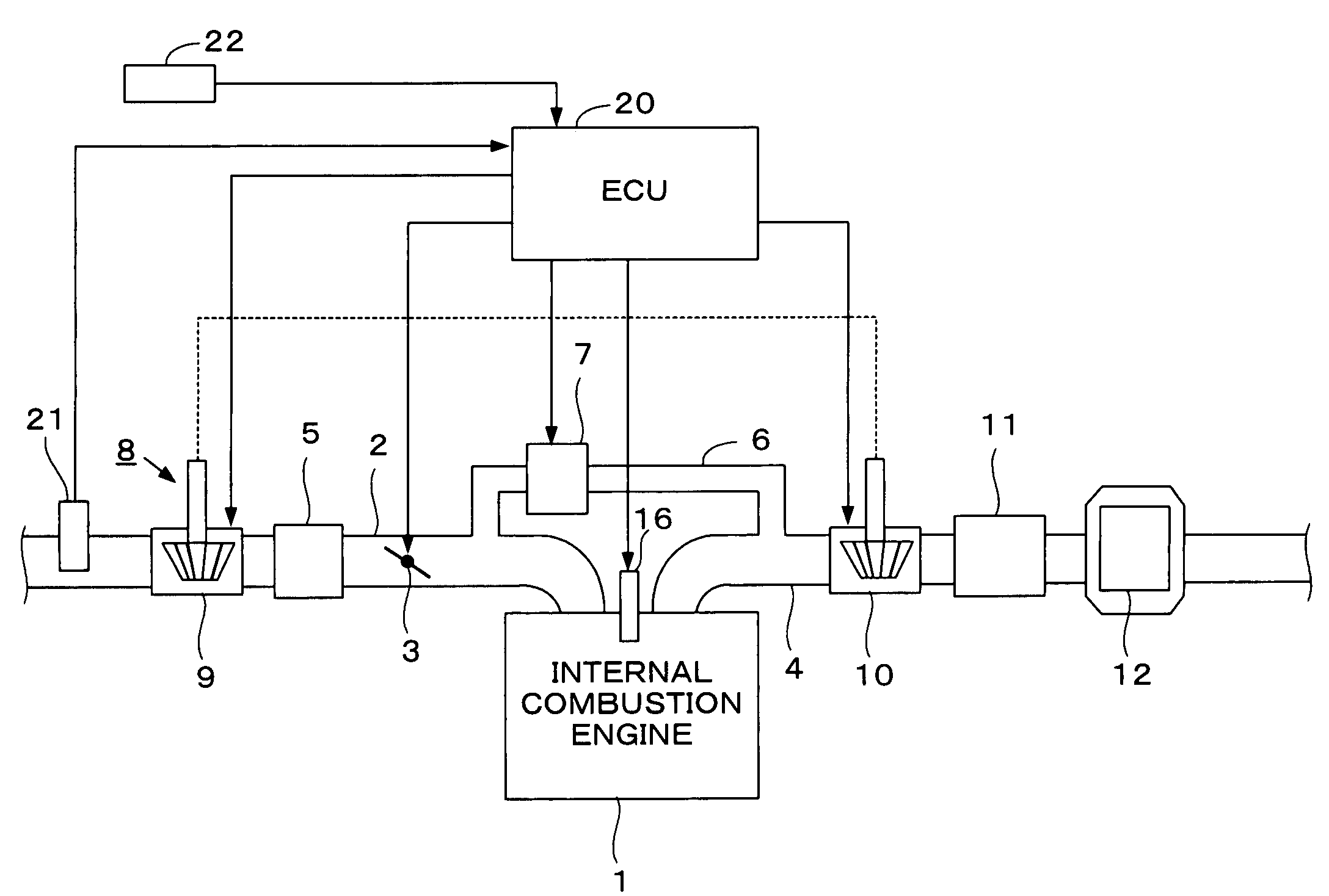
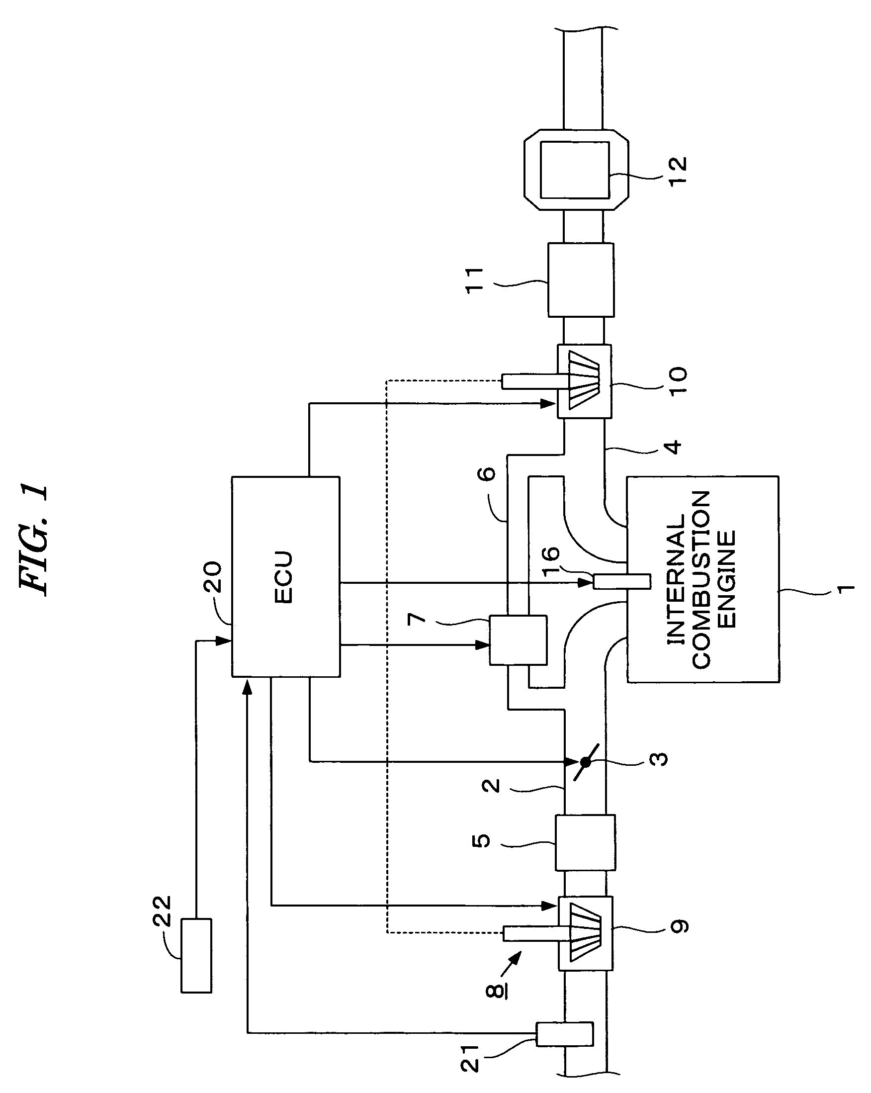
[0035]FIG. 1 is a schematic diagram illustrating the structural configuration of an internal combustion engine provided with an exhaust gas purifying apparatus and a control device according to an embodiment of the present invention. An internal combustion engine 1 (hereinafter referred to merely as “engine”) is a diesel engine in which fuel is injected directly into cylinders, wherein each cylinder is provided with a fuel injection valve 16. The fuel injection valve 16 is electrically connected to the electronic control unit 20 (hereinafter referred to as “ECU”). A valve opening period and a valve opening timing of the fuel injection valve 16 are both controlled by the ECU 20.

[0036] The engine 1 is provided with an intake pipe 2, an exhaust pipe 4, and a turbocharger 8. The turbocharger 8 has a turbine 10 driven by the kinetic energy of exhaust gases and a compressor 9 for c...


PUM

PropertyMeasurementUnit
Distanceaaaaaaaaaa
Threshold limitaaaaaaaaaa

Abstract

An exhaust gas purifying apparatus for an internal combustion engine includes a particulate filter for trapping particulates found in the exhaust gases of the engine. The regeneration process for burning the particulates trapped in the particulate filter is executed by performing post injection of fuel. The regeneration process is suppressed according to an amount of fuel injected during post injection.

Description

BACKGROUND OF THE INVENTION [0001] 1. Field of the Invention [0002] The present invention relates to an exhaust gas purifying apparatus for an internal combustion engine, and particularly, to the apparatus having a particulate filter, such as a diesel particulate filter, hereinafter referred to as DPF, which traps particulates, also referred to as particulate matter, in exhaust gases of the internal combustion engine. [0003] 2. Description of the Related Art [0004] A technique wherein a DPF is provided, which traps particulates in exhaust gases in the exhaust system of a diesel internal combustion engine and reduces an emission amount of the particulates, is widely used. Since there is a limit in the amount of particulates that can be trapped in the DPF, a regeneration process is timely performed wherein the particulates accumulated in the DPF are burned. The regeneration process is performed, for example, by executing a fuel injection during the exhaust stroke (hereinafter referred...

Claims


Application Information

Patent Timeline
IPC IPC(8): F01N3/00F01N5/04
CPCF01N2430/085F02D41/029F02D41/405Y02T10/44F02D2200/0812F02D2250/11F02D2041/228Y02T10/40Y10S55/05Y10S55/10Y10S55/30
Inventor CHIBA, ISAOMATSUKADO, RYUJI
Owner HONDA MOTOR CO LTD
Why Eureka
Try Eureka