
Ultrasonic welding apparatus

a welding apparatus and ultrasonic technology, applied in the direction of soldering apparatus, manufacturing tools,auxillary welding devices, etc., can solve the problems of reducing the efficiency of ultrasonic welding apparatus, and reducing the energy normally transferred to the workpiece to perform welds, etc., to achieve efficient installation and extraction, reduce manufacturing costs

Inactive Publication Date: 2006-11-16
FORD MOTOR CO +2
View PDF6 Cites 18 Cited by
  • Summary
  • Abstract
  • Description
  • Claims
  • Application Information

AI Technical Summary

Benefits of technology

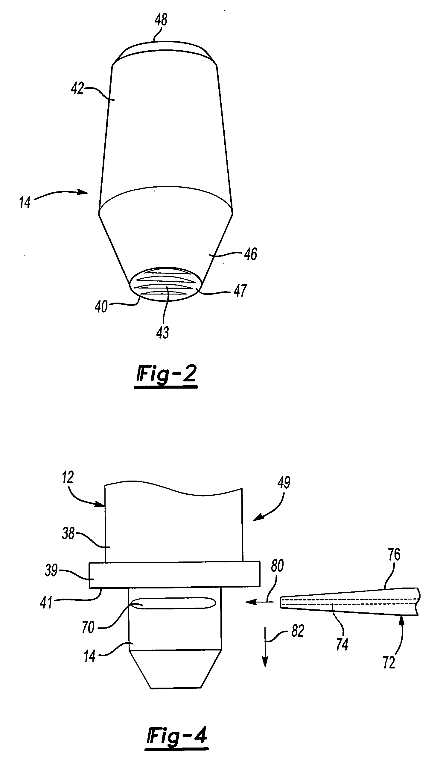
The present invention is an ultrasonic welding apparatus with a replaceable sonotrode. The sonotrode has a non-threaded outer peripheral surface, a gripping or contact surface, and a tapered surface on one end that mates with a correspondingly tapered aperture in the end of a reed of the ultrasonic welding apparatus. A rod, sized to fit within the passageway, extends through the reed and applies a force to the sonotrode to extract it. The sonotrode may include a slot or groove for easy removal, and it may also have an orientation or detent mechanism to align it properly with the reed. A reusable sonotrode holder is also provided. The invention allows for efficient installation and extraction of the sonotrode from the reed of the ultrasonic welding apparatus, and it reduces manufacturing costs.

Problems solved by technology

During the course of welding operations, the sonotrode will wear slowly.
It is also possible that some of the weldment material may build up on the sonotrode, potentially clogging the gripping or contact surface of the sonotrode, and reduce the efficiency of the ultrasonic welding apparatus as energy normally transferred to the workpiece to perform the weld is lost.
The more clogged or worn the gripping or contact surface of the sonotrode, the more its efficiency is reduced.
The raw stock, typically high-grade tool steel, is expensive.
Besides being costly from a material standpoint, i.e., much of the raw stock is removed and discarded during the machining process; the machining process is labor intensive, which also increases sonotrode costs.
Further, since it may not be feasible to clean the contact surface of the sonotrode, there is a need for a sonotrode that requires less machining or fabrication time to produce a finished sonotrode which correspondingly reduces the overall cost or expense of the sonotrode.

Method used


Image

  • Ultrasonic welding apparatus
  • Ultrasonic welding apparatus
  • Ultrasonic welding apparatus

Examples


Embodiment Construction

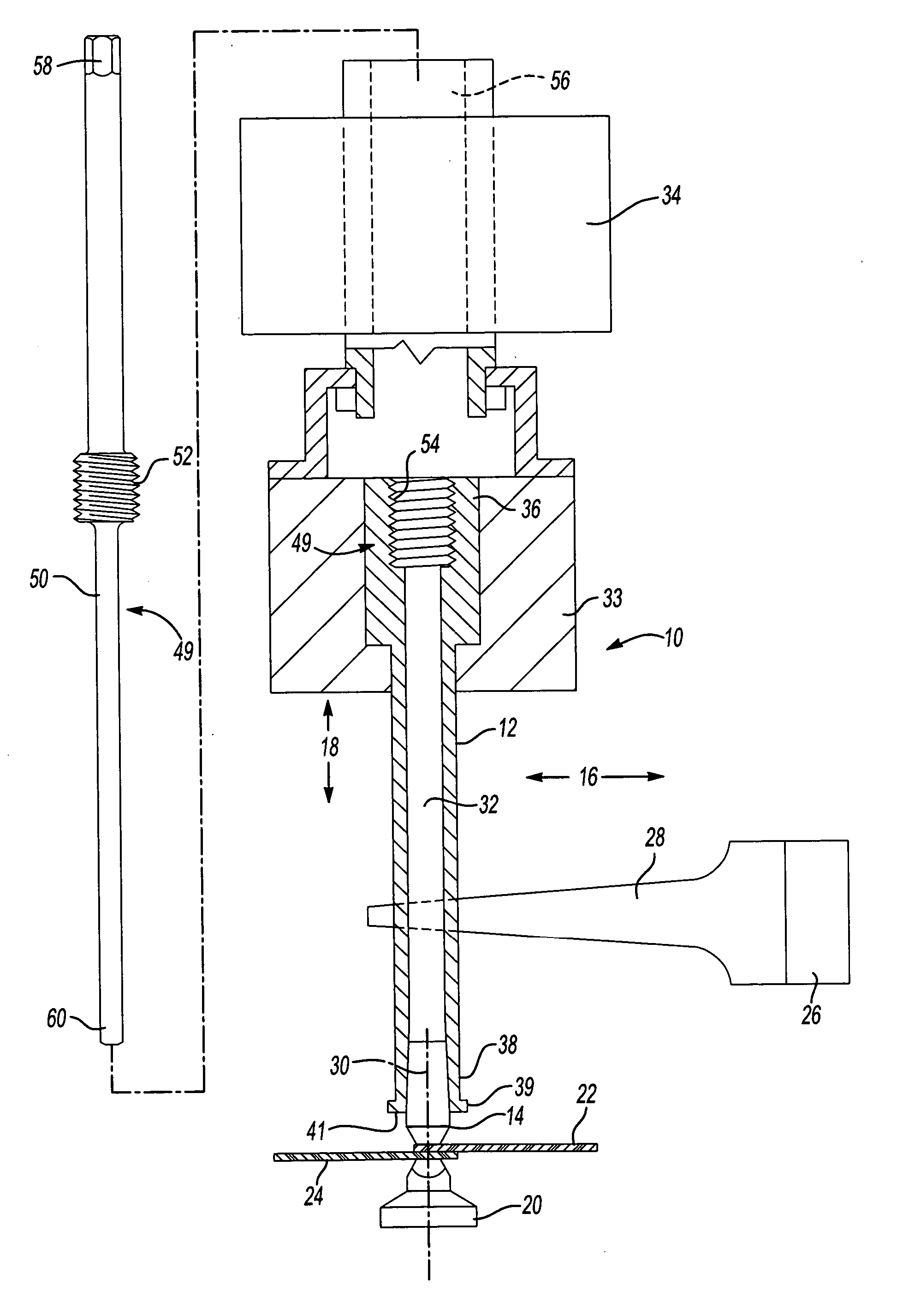
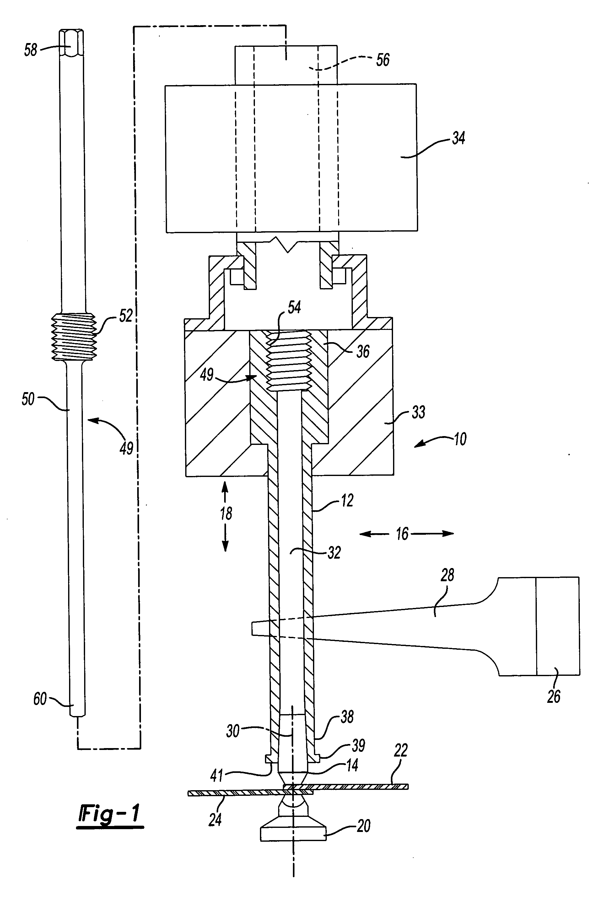
[0026]FIG. 1 shows an ultrasonic welding apparatus, seen generally at 10, according to one embodiment of the present invention. The ultrasonic welding apparatus 10 includes a reed 12 having a sonotrode 14 mounted at one end thereof. The reed 12 is mounted for movement in a side to side or horizontal direction of vibration, shown by the arrow 16. The reed 12 also moves in a vertical manner, shown by the arrow 18, and in cooperation with an anvil 20 clamps first 22 and second 24 workpieces in position. Once the workpieces 22, 24 are clamped, a transducer 26, connected to the reed 12 by a wedge 28, vibrates the reed 12 at a high frequency (typically 15 to 40 kHz) to impart energy through the sonotrode 14 to the first 22 and second 24 workpieces at a location between the sonotrode 14 and the anvil 20 to create a bond or weld at the interface or adjacent surfaces 30 of the workpieces 22, 24. As used herein, the term sonotrode generally refers to a tool attached to the reed of an ultrason...


PUM

PropertyMeasurementUnit
frequencyaaaaaaaaaa
lengthaaaaaaaaaa
contact surfaceaaaaaaaaaa

Abstract

An ultrasonic welding apparatus having an extractable sonotrode. The sonotrode having a non-threaded outer peripheral surface and a tapered mating surface that meets with a correspondingly tapered aperture formed in the end of the reed of the ultrasonic welding apparatus. In the preferred embodiment the ultrasonic welding apparatus includes a sonotrode removal mechanism for extracting the sonotrode from the reed.

Description

FEDERAL SPONSORSHIP [0001] The U.S. Government has a paid-up license in this invention and the right, in limited circumstances, to require the patent owner to license others on reasonable terms as provided for by the terms of Contract No. 70NANB3H3015 awarded by the National Institute of Standards and Technology.CROSS-REFERENCE TO RELATED APPLICATIONS [0002] Not Applicable BACKGROUND OF THE INVENTION [0003] 1. Field of the Invention [0004] The present invention relates generally to an ultrasonic welding apparatus; and, more specifically, to a replaceable sonotrode tip for use with an ultrasonic welding apparatus. [0005] 2. Description of Related Art [0006] Ultrasonic welding of various materials is known. The process involves vibrating overlapping workpieces clamped between a sonotrode and an anvil. Frictional forces occurring between the vibrating workpieces create a bond or weld that occurs at the interface between the workpieces, effectively joining them to one another. Various s...

Claims


Application Information

Patent Timeline
Patent Type & Authority Applications(United States)
IPC IPC(8): B23K37/00
CPCB23K20/10
Inventor REATHERFORD, LARRYHETRICK, ELIZABETH T.WILKOSZ, DANIEL E.WALSH, JOSEPHSKOGSMO, JAN
Owner FORD MOTOR CO
Learn More