
Optical beam-shaper

a beam-shaper and optical technology, applied in the field of optical beam-shapers, can solve the problems of large waste of beams, poor beam-shaping using diffractive optics, and particular disadvantages of beam-shapers using diffractive optics, and achieve the effect of enhancing performance and minimizing undesired coherent interferen

Inactive Publication Date: 2006-11-16
BECTON DICKINSON & CO
View PDF8 Cites 47 Cited by
  • Summary
  • Abstract
  • Description
  • Claims
  • Application Information

AI Technical Summary

Benefits of technology

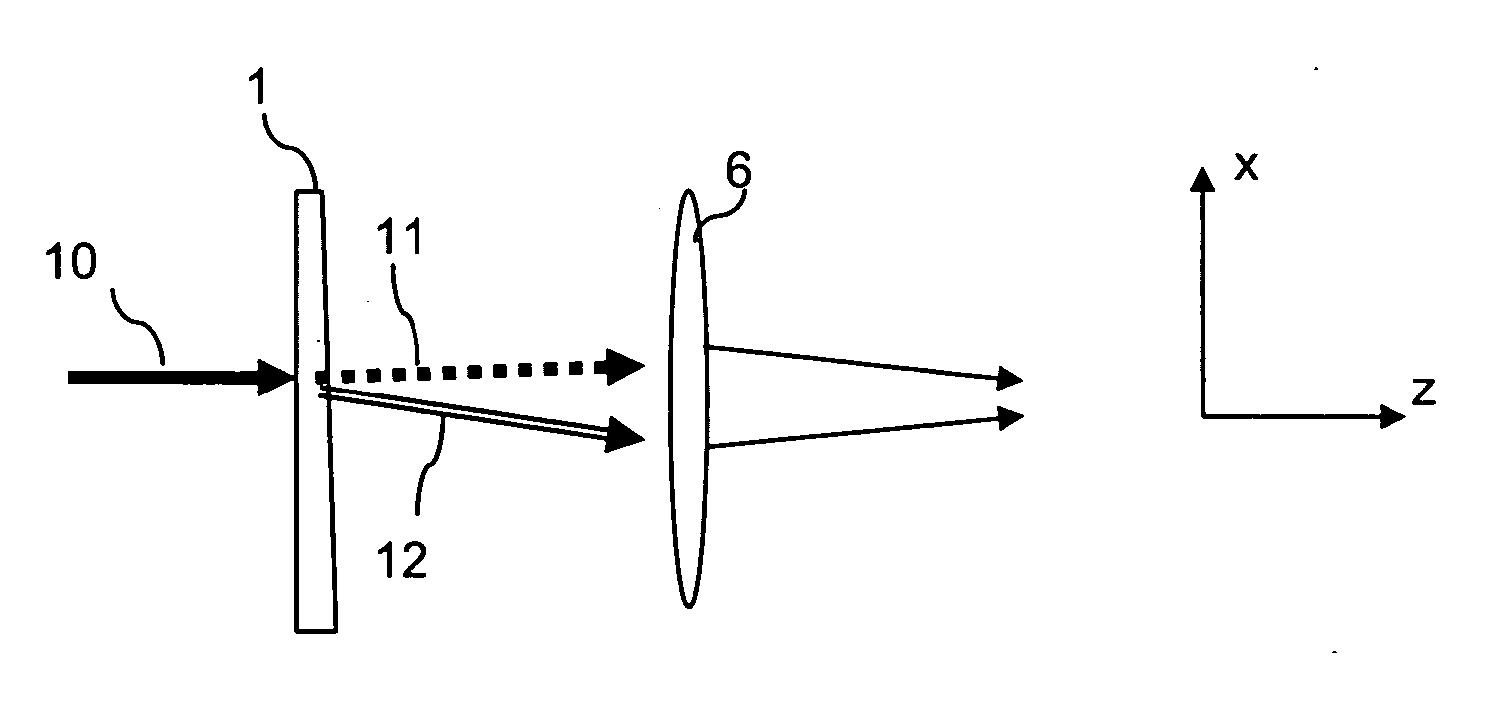
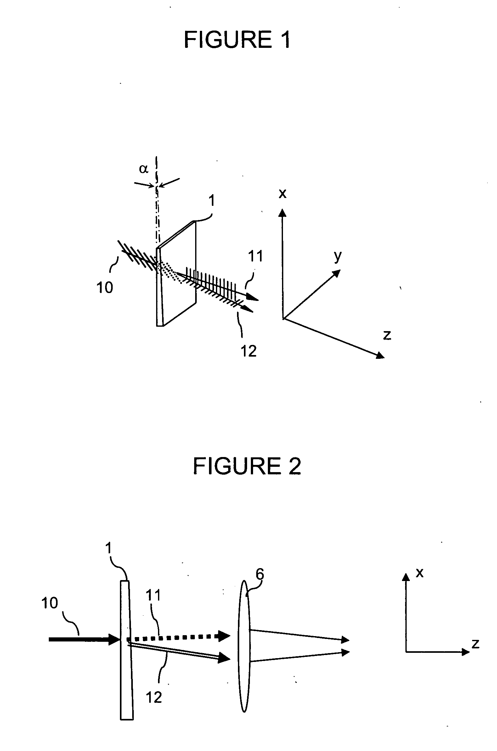
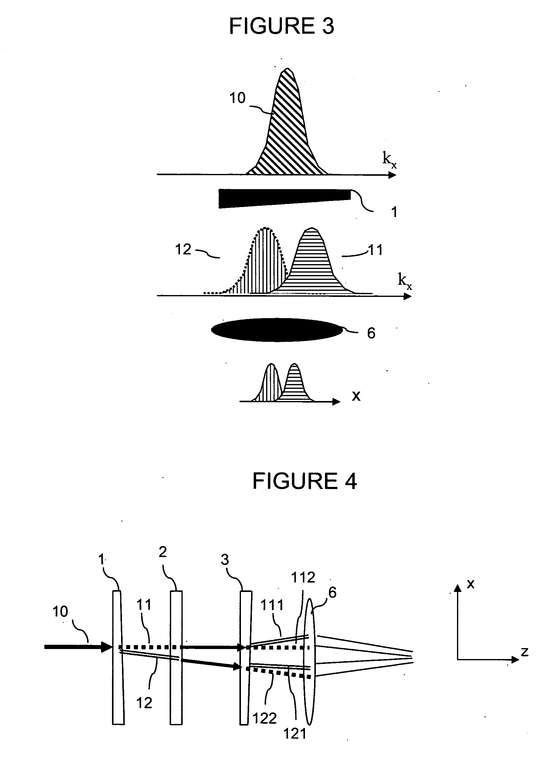
[0012] In some embodiments of the present invention, the beam-shaping optics comprise a plurality of beam-splitting elements. The plurality of beam-splitting elements split the light into a greater multiplicity of output beams such that a single combined beam having the desired intensity profile is formed from the superposition of the output beams. The formation of the final combined output beam from a greater number of component output beams enables more refined reshaping of the beam and closer approximations to a desired beam profile, such as an ideal top-hat profile.
[0013] The plurality of beam-splitting elements may be oriented such that the multiplicity of output beams diverge along a single axis, resulting in a combined output beam that is reshaped along a single axis. Alternatively, the plurality of beam-splitting elements may be oriented such that the output beams diverge along two, preferably orthogonal axes, resulting in a combined output beam that is reshaped along the two axis. Combinations of these embodiments enable more refined reshaping of the beam profile in both profile axes.
[0015] An advantage of using wedges of a birefringent material as beam-splitting elements is that the divergent output beams are polarized in directions perpendicular to each other. The orthogonal polarizations minimize undesired coherent interferences between the output beams. This property of the beam-shapers of the present invention represents a significant advantage over previously described beam-shapers.
[0016] Although, in preferred embodiments, the beam-splitting elements consist of a wedge of a birefringent material, it will be clear to one of skill in the art that other optical elements, such as a diffraction grating beam-splitting element can be used, either alone or in combination with elements made from birefringent material. It will also be clear that certain advantages provided by the preferred beam-splitting elements, e.g., the minimization of undesired coherent interferences between the split beams, result from the properties of birefringent materials and, thus, enhanced performance is achieved using the preferred embodiments.
[0022] In other embodiments, a higher number of beam-splitting elements are used in order to produce a greater number of output beams. The superposition of greater number of beams allows for more control over the final combined beam profile and enables better approximations to an desired beam profile, For example, the accuracy of an approximation of an ideal top-hat beam profile can be increased using a superposition of a greater number of narrower output beams. The desired number of beam-splitting elements will be application-dependent. It is expected that, in most applications, there will be a tradeoff between the accuracy of the approximation and the simplicity (e.g., low part count) of the beam-shaper, and a suitable beam-shaper can be designed following the guidance provided herein.

Problems solved by technology

In order to obtain uniform illumination across the width of the core stream, the focal spot is widened, which results in a significant portion of the beam being wasted.
However, beam-shapers using diffractive optics have distinct disadvantages in particular applications because of their sensitivity to the input beam profile and because the beam shaping is wavelength-dependent.
The variability in the output beam profile results in poor beam shaping using diffractive optics.
The breadth of the laser bandwidth results in poor beam shaping using diffractive optics.

Method used


Image

  • Optical beam-shaper
  • Optical beam-shaper
  • Optical beam-shaper

Examples


example 1

Beam-Shaper for Flow Cytometry

[0078] A beam-shaper essentially as shown in FIGS. 6 and 7 was made and tested. Half-wave plates and wedge elements meeting the following specifications were obtained from Red Optronics (Mountainview, Calif.), the wedge elements as custom ordered components: [0079] Element dimensions: 9.9±0.1 mm diameter [0080] Wavefront distortion [0081] Coating: R[0082] Elements 4, 2, and 5: zero order half-wave plates [0083] Retardation tolerance: [0084] Parallelism: [0085] no epoxy in optical path [0086] Wedge element 1: α1=1.569°±10 arc seconds [0087] Wedge element 2: α2=0.807°±10 arc seconds

[0088] The beam-shaper was assembled such that all angles were within 0.5° of the specified angles. Element 2, oriented in a plane perpendicular to the z-axis, was empirically adjusted to give optimum results, which were obtained, in this case, at an angle between the optical axis and the x-axis of 23.47°.

[0089] The beam-shaper was tested using an input beam from a 375 nm UV...

example 2

Beam-Splitter Design

[0095] The present example describes the design of beam-shaper of the present invention suitable for a specified application.

[0096] In overview, the design of a beam-shaper is carried out by first expressing the intensity profile of the combined output beam as a function of the intensity profile of the input beam and the separation angles of beam-splitting elements, and then optimizing this function to obtain the desired beam profile. Typically, the intensity profile of the input beam is fixed by the choice of the light source, so that in the optimization of the intensity profile of the combined output beam, only the separation angles of beam-splitting elements are treated as input variables. However, if the intensity profile of the input beam can be varied, optimization can be carried out over both the input intensity profile and the angle parameters.

[0097] Optimization of the intensity profile, expressed as a function of the input intensity profile and angle...


PUM


Abstract

The present invention provides beam-shaping optics for transforming an approximately gaussian beam profile into a (nearly) uniform distribution over a specified spot area. The beam-shaping optics provide significant advantages over existing beam-shapers in that they are less sensitive to variations in the input beam profiles and can be used over a range of frequencies.

Description

CROSS REFERENCE TO RELATED APPLICATIONS [0001] This application claims priority to U.S. provisional application No. 60 / 680,729, filed May 13, 2005, which is incorporated herein by reference.BACKGROUND OF THE INVENTION [0002] 1. Field of the Invention [0003] The present invention relates to the field of optics and, in particular, to laser optics. [0004] 2. Description of Related Art [0005] Particle analyzers, such as flow and scanning cytometers, are well known analytical tools that enable the characterization of particles on the basis of optical parameters such as light scatter and fluorescence. In a flow cytometer, for example, particles such as molecules, analyte-bound beads, or individual cells in a fluid suspension are passed by one or more detectors in which the particles are exposed to an excitation light, typically one or more lasers, and the light scattering and fluorescence properties of the particles are measured. Each particle, or subcomponents thereof, may be labeled wit...

Claims


Application Information

Patent Timeline
Patent Type & Authority Applications(United States)
IPC IPC(8): G01J4/00
CPCG02B5/3083G02B27/0972G02B27/0927G02B27/0905
Inventor CHEN, YONG QIN
Owner BECTON DICKINSON & CO
Learn More