Capacitor

a capacitor and dielectric material technology, applied in the direction of fixed capacitor details, plastic/resin/waxes insulators, insulating bodies, etc., can solve the problems of noise, noise, and malfunction caused by power supply voltage changes, and achieve the effect of large capacity and high relative dielectric constan

Inactive Publication Date: 2006-11-16
FUJI ELECTRIC HLDG CO LTD
View PDF1 Cites 21 Cited by
  • Summary
  • Abstract
  • Description
  • Claims
  • Application Information

AI Technical Summary

Benefits of technology

[0023] As described in detail below, according to the present invention, there is provided a capacitor capable of exhibiting a high relative dielectric constant and a large capacity even in the case of using an organic insulating material with...

Problems solved by technology

However, surface mounted components such as capacitors still occupy large areas of printed circuit boards.
This is a major obstacle in further miniaturizing the electronic apparatuses.
As frequency is increased and voltage is lowered in integrated circuits, malfunctions caused by changes of power supply voltage due to noise is becoming a serious problem.
The problem has arisen because the allowable range of the power supply voltage is reduced when the voltage is lowered.
Therefore, with future increases in operating frequency, the inductance components of devices and the inductance components of wirings are expected to create noise.
However, such dielectric materials have problems.
Ceramics-based mat...

Method used


Image

  • Capacitor
  • Capacitor
  • Capacitor

Examples


example 1

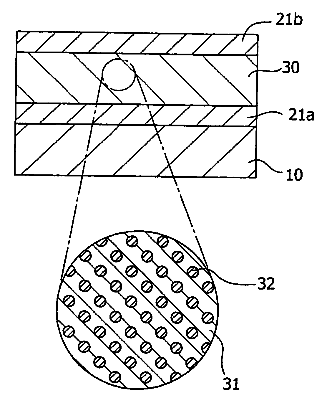
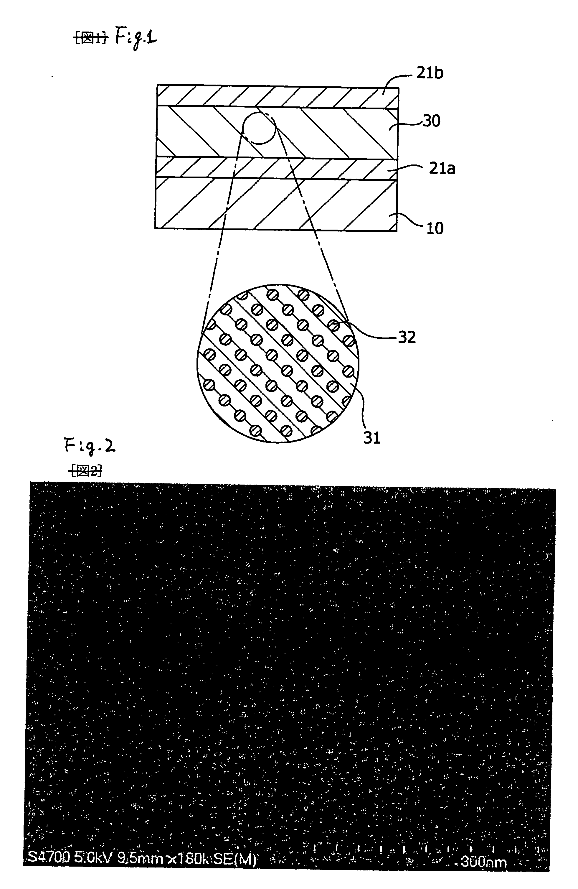
[0066] A capacitor having the structure shown in FIG. 1 was produced in the following manner.

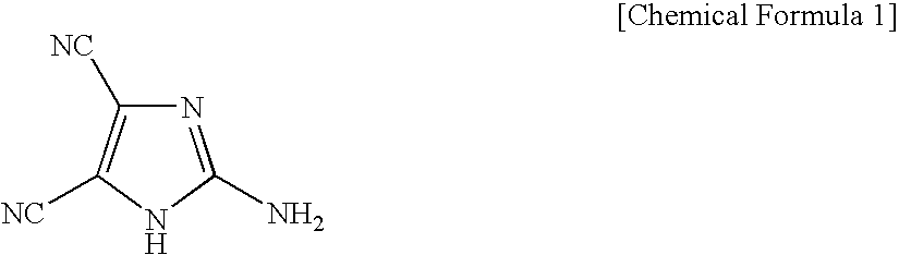
[0067] A glass substrate was used as the substrate 10, and an aluminum thin film was formed as the electrode layer 21a by a vacuum deposition method. Then, in succession, 2-amino-4,5-imidazole dicyanate (available from Tokyo Kasei Kogyo Co., Ltd., Catalog Number A1292) as the organic insulating material 31 and aluminum as the metal microparticles 32 were codeposited to form the dielectric material layer 30, and a a thin film of aluminum was formed thereon as the electrode layer 21b, to produce a capacitor of Example 1.

[0068] The electrode layer 21a, the dielectric material layer 30, and the electrode layer 21b were formed such that the thicknesses thereof were 100 nm, 100 nm, and 100 nm, respectively. The average particle diameter of aluminum as the metal microparticles 32 was about 25 nm. The deposition was carried out by a diffusion pump exhaust deposition apparatus under a vacuum of 3×1...

example 2

[0069] 2-Amino-4,5-imidazole dicyanate was used as the organic insulating material 31, gold was used as the metal microparticles 32, and they were codeposited to form a film as the dielectric material layer 30. A capacitor was produced under the same conditions as Example 1 except for the use of gold instead of aluminum.

example 3

[0070] 2-Amino-4,5-imidazole dicyanate was used as the organic insulating material 31, copper was used as the metal microparticles 32, and they were codeposited to form a film as the dielectric material layer 30. A capacitor was produced under the same conditions as Example 1 except for the use of copper instead of aluminum.


PUM

PropertyMeasurementUnit
Temperatureaaaaaaaaaa
Dielectric polarization enthalpyaaaaaaaaaa
Energy levelaaaaaaaaaa

Abstract

A flexible capacitor easily produced at low temperature. The capacitor has a dielectric material layer and two electrodes sandwiching the layer. The dielectric material layer contains metal microparticles and/or an organic charge trapping material in an organic insulating material, and the metal microparticles, have an ionization potential and an electron affinity at an energy level between the ionization potential and the electron affinity of the organic insulating material. Once the metal microparticles are charged by applying a voltage, the charge is trapped in the metal microparticles, due to the metal microparticles' energy level relative to the organic insulating material. The trapped charge acts in the same manner as dielectric polarization in the dielectric material, so that extremely large dielectric constant can be obtained practically even when the organic insulating material has a small dielectric constant.

Description

BACKGROUND OF THE INVENTION [0001] 1. Technical Field [0002] The present invention relates to a dielectric material and a capacitor, particularly a capacitor for use as an electronic circuit incorporated in printed boards or integrated circuits. [0003] 2. Background Art [0004] Recently, size, thickness, and weight of electric apparatuses have been reduced, electric circuits have been miniaturized and digitalized, and therewith there have been increasing demands of improving size, performance, and reliability of electronic components. Under such circumstances, also capacitors are required to have a small size and a high capacitance. [0005] However, surface mounted components such as capacitors still occupy large areas of printed circuit boards. This is a major obstacle in further miniaturizing the electronic apparatuses. To overcome the problem, there have been attempts to incorporate some electronic parts, such as capacitors, in circuit boards (for example, see JP-A-10-56251 and JP-...

Claims


Application Information

Patent Timeline
IPC IPC(8): H01G4/06H01B3/00H01B3/30H01B17/64H01G4/14H01G4/18H01G4/20
CPCH01B3/004H01B3/301H01G4/206H01G4/14H01G4/18H01B3/303
Inventor KATO, HISATOKAWAKAMI, HARUOYAMASHIRO, KEISUKE
Owner FUJI ELECTRIC HLDG CO LTD
Why Eureka
Try Eureka