
Hydrophobic surface coating with low wetting hysteresis, method for depositing same, microcomponent and use

a technology of hydrophobic surface coating and wetting hysteresis, which is applied in the direction of chemical vapor deposition coating, ion implantation coating, coating, etc., can solve the problem of less effect of wetting hysteresis on drop movement, greater wetting hysteresis of surface coating, and more difficulty in dropping water. to move, good hydrophobicity, and low wetting hysteresis

Active Publication Date: 2011-08-02
COMMISSARIAT A LENERGIE ATOMIQUE ET AUX ENERGIES ALTERNATIVES
View PDF11 Cites 87 Cited by
  • Summary
  • Abstract
  • Description
  • Claims
  • Application Information

AI Technical Summary

Benefits of technology

The invention relates to a surface coating for microcomponents that has low wetting hysteresis, high hydrophobicity, and a high relative dielectric constant. The coating consists of a top thin layer made of SiCxOy:H and SiCx'Ny':H, and a bottom thin layer made of SiCx'Ny':H. The method for depositing the coating is chemical vapor deposition using organosilanes, which can be plasma enhanced. The invention also provides a microcomponent with the surface coating, which can easily receive and move liquid drops on its surface.

Problems solved by technology

However, the electrowetting principle requires the free surface on which the drop is placed to be very hydrophobic.
However, as the hydrophobicity and wetting hysteresis parameters are related, the more hydrophobic a surface is, the lesser the effect the wetting hysteresis has on movement of the drop.
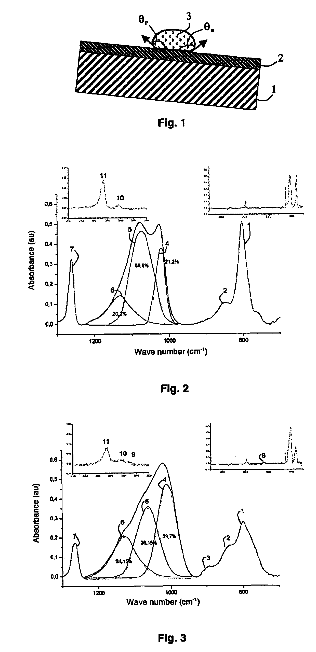
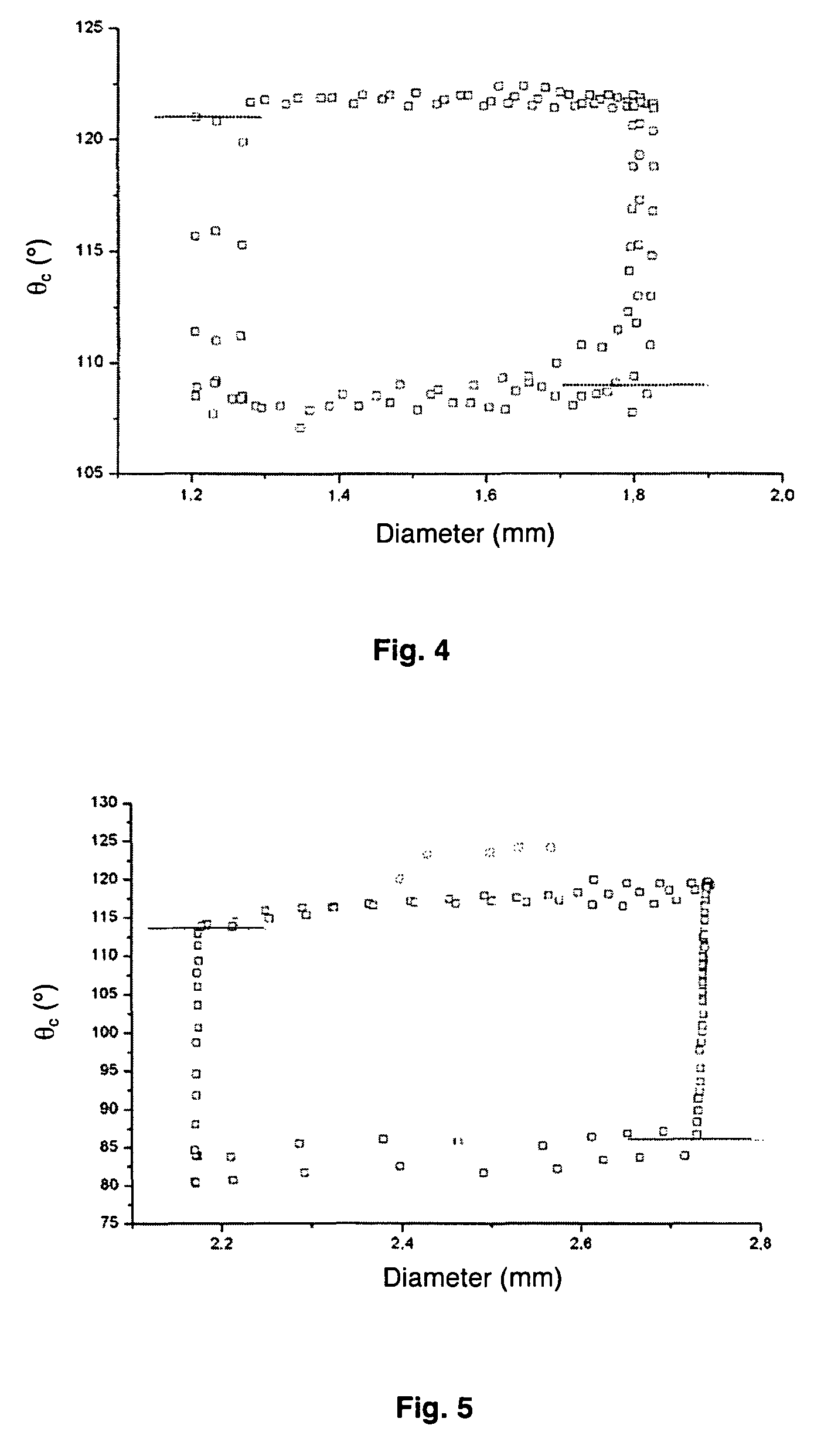
The greater this difference, the greater the wetting hysteresis of the surface coating and the more difficulty the drop of water has to move.
Finally, Teflon® presents the drawback of generally being spin coated.
This technique is however only applicable to perfectly flat surfaces, which limits the use of a Teflon® coating in the electrowetting-on-dielectric field.
This compound is not however sufficiently hydrophobic, the contact angle being equal to 90°, and it comprises a too high wetting hysteresis to enable it to be used in a device using the electrowetting-on-dielectric phenomenon.

Method used


Image

  • Hydrophobic surface coating with low wetting hysteresis, method for depositing same, microcomponent and use
  • Hydrophobic surface coating with low wetting hysteresis, method for depositing same, microcomponent and use
  • Hydrophobic surface coating with low wetting hysteresis, method for depositing same, microcomponent and use

Examples


Embodiment Construction

[0029]According to the invention, a hydrophobic surface coating comprises at least one upper layer consisting of a compound selected among SiCxOy:H and SiCx′Ny′:H, with x comprised between 1.4 and 2 and y comprised between 0.8 and 1.4 and with x′ comprised between 1.2 and 1.4 and y′ comprised between 0.6 and 0.8. The upper thin layer preferably has a thickness less than or equal to 1 micrometer.

[0030]What is meant by SiCxOy:H is a compound selected among carbon-doped amorphous hydrogenated silicon oxides, the atomic proportion of carbon compared with the atomic proportion of oxygen corresponding to the ratio x / y.

[0031]What is meant by SiCx′Ny′:H is a compound selected among carbon-doped amorphous hydrogenated silicon nitrides, the atomic proportion of carbon compared with the atomic proportion of nitrogen corresponding to the ratio x′ / y′.

[0032]Such a choice of compounds able to form the upper layer of the hydrophobic surface coating is determined by the nature of the chemical bonds ...


PUM

PropertyMeasurementUnit
thicknessaaaaaaaaaa
thicknessaaaaaaaaaa
relative dielectric constantaaaaaaaaaa

Abstract

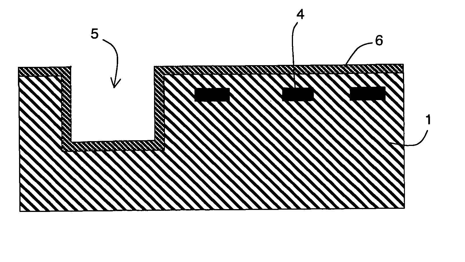
A hydrophobic surface coating, preferably obtained by chemical vapor deposition, comprises at least an upper thin layer formed by a compound selected from the group consisting of SiCxOy:H with x comprised between 1.4 and 2 and y comprised between 0.8 and 1.4 and SiCx′Ny′:H with x′ comprised between 1.2 and 1.4 and y′ comprised between 0.6 and 0.8, so as to obtain a free surface with a low wetting hysteresis. Such a hydrophobic surface coating can be arranged on the free surface of a microcomponent comprising at least one substrate provided with, an electrode array and particularly suitable for moving drops of liquid by electrowetting on dielectric.

Description

BACKGROUND OF THE INVENTION[0001]The invention relates to a hydrophobic surface coating.[0002]The invention also relates to a method for depositing a such surface coating, a microcomponent comprising at least a substrate provided with an electrode array and having a surface designed to receive a drop of liquid, and the use of one such microcomponent.STATE OF THE ART[0003]In a large number of fields where analysis of aqueous solutions is involved, such as the field of chemical, biological, biochemical and environmental analysis, the medical field or quality control, the development of microtechnologies has enabled microcomponents forming labs-on-chip to be achieved. Such labs-on-chip enable to miniaturize the volumes of liquid to be analyzed, while at the same time increasing the speed and sensitivity of the measurements. These microcomponents generally comprise channels or cavities which can generate interactions between the solutes and the walls of the channels or of the cavities a...

Claims


Application Information

Patent Timeline
Patent Type & Authority Patents(United States)
IPC IPC(8): B32B27/32
CPCC23C16/30C23C16/36G01N33/5438G01N33/54393B01L3/5027
Inventor PLISSONNIER, MARCGAILLARD, FREDERICFOUILLET, YVES
Owner COMMISSARIAT A LENERGIE ATOMIQUE ET AUX ENERGIES ALTERNATIVES
Learn More