
Hydrolysis of chemical hydrides utilizing hydrated compounds

Inactive Publication Date: 2006-11-16
LYNNTECH POWER SYST
View PDF92 Cites 29 Cited by
  • Summary
  • Abstract
  • Description
  • Claims
  • Application Information

AI Technical Summary

Benefits of technology

[0010] In still another aspect, a hydrogen generator is provided which comprises (a) a reaction chamber; (b) a first material disposed in the reaction chamber and selected from the group consisting of hydrides, borohydrides and alanes; and (c) a second material disposed in the reaction chamber and selected from the group consisting of hydrates. The amount of the first material in the reaction chamber is

Problems solved by technology

However, for some applications, the exothermic nature of the hydrolysis reaction is a drawback from a system perspective, especially when thermal management is an issue.
Unfortunately, many hydrogen-generating materials exhibit significant heat spikes in the hydrolysis reaction, especially in the early stages.
Even when it is possible to eliminate such spikes, the amount of heat generated by the hydrolysis reaction itself is often considerable.

Method used


Image

  • Hydrolysis of chemical hydrides utilizing hydrated compounds
  • Hydrolysis of chemical hydrides utilizing hydrated compounds
  • Hydrolysis of chemical hydrides utilizing hydrated compounds

Examples


first embodiment

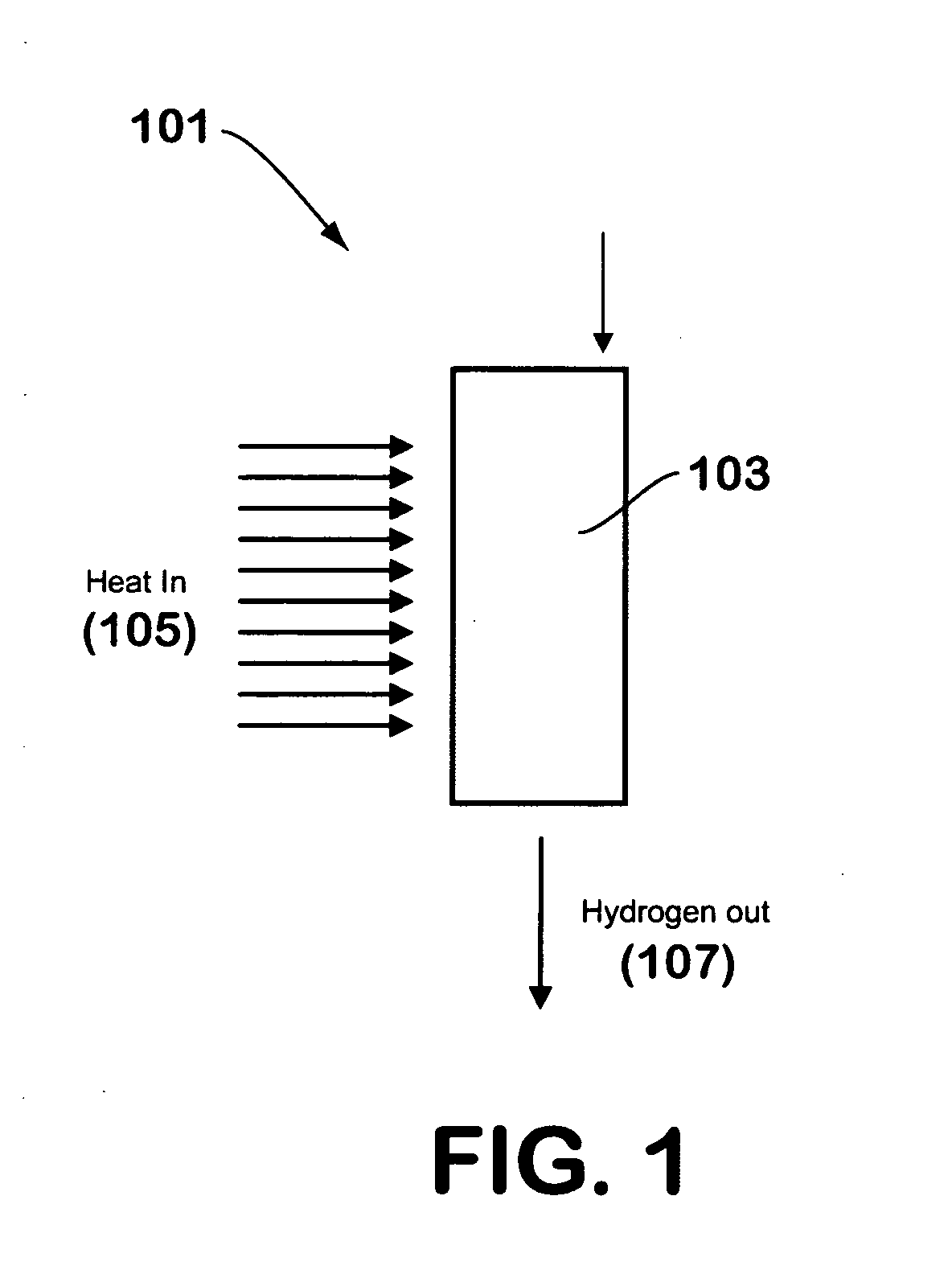
[0024]FIG. 1 illustrates a hydrogen generator 101 made in accordance with the teachings herein. In this embodiment, a suitable hydrogen-generating compound 103, such as, for example, a hydride, borohydride, borane, alane, or aminoborane, is combined with a salt hydrate or other water-generating material and a catalyst (if needed). The mixture may be in a powder form, or may be in the form of granules or pellets. For example, a pneumatic press may be utilized to generate pellets of a desired size or shape from a powder mixture of the hydrogen-generating compound and the water-generating material.

[0025] To begin the reaction, thermal energy 105 is supplied to the mixture in a localized region to initiate the dehydration reaction that generates water from the water-generating material. Once generated, the water is available for the hydrolysis reaction that evolves hydrogen gas, and the hydrogen gas so evolved exits the reaction chamber through a hydrogen gas outlet 107. If the hydrolys...

second embodiment

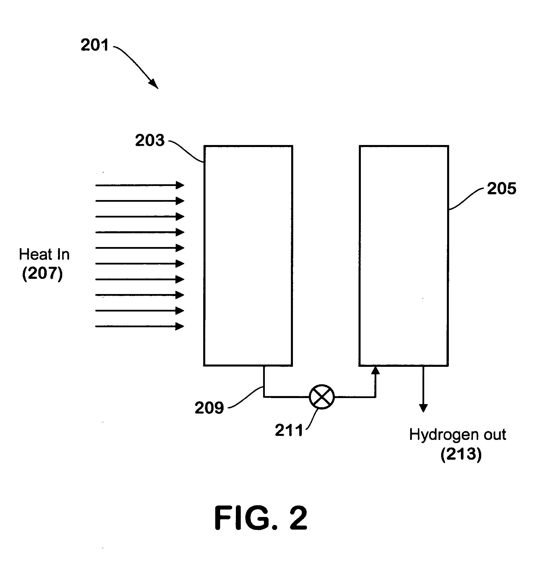
[0027]FIG. 2 illustrates a hydrogen generator made in accordance with the teachings herein. In this embodiment, the hydrogen generator 201 comprises first 203 and second 205 distinct chambers. The first chamber 203 contains a material that is capable of undergoing a dehydration reaction to yield water, preferably with the application of heat 207. Such a material may be, for example, a hydrated salt selected from the group consisting of acetates, bromides, chlorides, formides, fluorides, iodides, phosphates, and thiosulfates, and is preferably a sulfate of aluminum, beryllium, calcium, iron, magnesium, potassium, or sodium. The hydrated compound releases water at specific temperatures, absorbing thermal energy in the process.

[0028] The hydrogen generator is further provided with a conduit 209 which conducts water released by the hydrated compound from the first chamber 203 into the second chamber 205. The conduit may be equipped with a suitable valve 211 or other control means which ...


PUM


Abstract

A method for dissipating heat in a hydrogen generator, comprising the steps of (a) providing a first chamber containing a first material selected from the group consisting of hydrates, (b) providing a second chamber containing a second material selected from the group consisting of hydrides and borohydrides, (c) causing the first material to undergo an endothermic reaction to evolve water, and (d) transporting a portion of the evolved water from the first chamber into the second chamber such that the second material undergoes an exothermic reaction to evolve hydrogen gas.

Description

CROSS-REFERENCE TO RELATED APPLICATION [0001] This application claims priority to U.S. provisional patent application No. 60 / 653,707, filed 17 Feb. 2005, and having the same title.STATEMENT OF GOVERNMENT RIGHTS [0002] This invention was made with government support under contract W15P7T-04-C-P415 awarded by the Department of Defense (Army). The government has certain rights in this invention.FIELD OF THE DISCLOSURE [0003] The present disclosure relates generally to methods of hydrolysis of chemical hydrides, and more specifically to methods of hydrolysis of chemical hydrides that utilize water-generating compounds for hydrolysis rather than simply water. BACKGROUND OF THE DISCLOSURE [0004] Hydrogen generators are devices that generate hydrogen gas for use in fuel cells, combustion engines, and other devices, frequently through the evolution of hydrogen gas from hydrides or borohydrides and other hydrogen-generating materials. Sodium borohydride (NaBH4) has emerged as a particularly ...

Claims


Application Information

Patent Timeline
IPC IPC(8): C09K3/00C01B3/02B01J19/00
CPCB01J8/009Y02E70/30B01J8/0449B01J8/0457B01J19/2475B01J19/249B01J2208/00309B01J2208/00398B01J2208/00415B01J2208/00716B01J2219/00038B01J2219/00135B01J2219/0015B01J2219/192B01J2219/1923B01J2219/194B01J2219/1947B01J2219/2453B01J2219/2454B01J2219/2465B01J2219/2466B01J2219/2475B01J2219/2481B01J2219/2485B01J2219/2486B01J2219/2488B01J2219/249C01B3/065F28D20/003H01M8/065Y02E60/142Y02E60/362Y02E60/50B01J8/025Y02E60/14Y02E60/36Y02P20/10
Inventor CISAR, ALANSALINAS, CARLOSWITHERS-KIRBY, SANDRAFIEBIG, BRAD
Owner LYNNTECH POWER SYST
Learn More