Method of manufacturing carbon nanotube

Inactive Publication Date: 2002-07-11
HONDA MOTOR CO LTD
View PDF3 Cites 59 Cited by
  • Summary
  • Abstract
  • Description
  • Claims
  • Application Information

AI Technical Summary

Benefits of technology

0023] Preferably, the auxiliary catalyst is mixed in an amount in excess of 0.1 atomic % of the total amount of the main and auxiliary catalysts. If the amount of the auxiliary catalyst were equal to or less than 0.1 atomic % of the total amount of the main and auxiliary catalysts, then no sufficient heat of formation would be obtained.
0024] The above and other objects, features, and advantages of the present invention will become apparent from the following description when taken in conjunction with the accompanying drawings which illustrate a preferred embodiment of the present invention by way of example.
0025] FIG. 1 is a schematic view of an arc discharging system for use in a method of manufacturing a carbon nanotube according to the present invention;
0026] FIG. 2 is a cross-sectional view of a graphite electrode for use in the method of manufacturing a carbon nanotube according t

Problems solved by technology

Each of the materials for use as the main and auxiliary catalysts may be subs

Method used


Image

  • Method of manufacturing carbon nanotube
  • Method of manufacturing carbon nanotube
  • Method of manufacturing carbon nanotube

Examples


Embodiment Construction

:

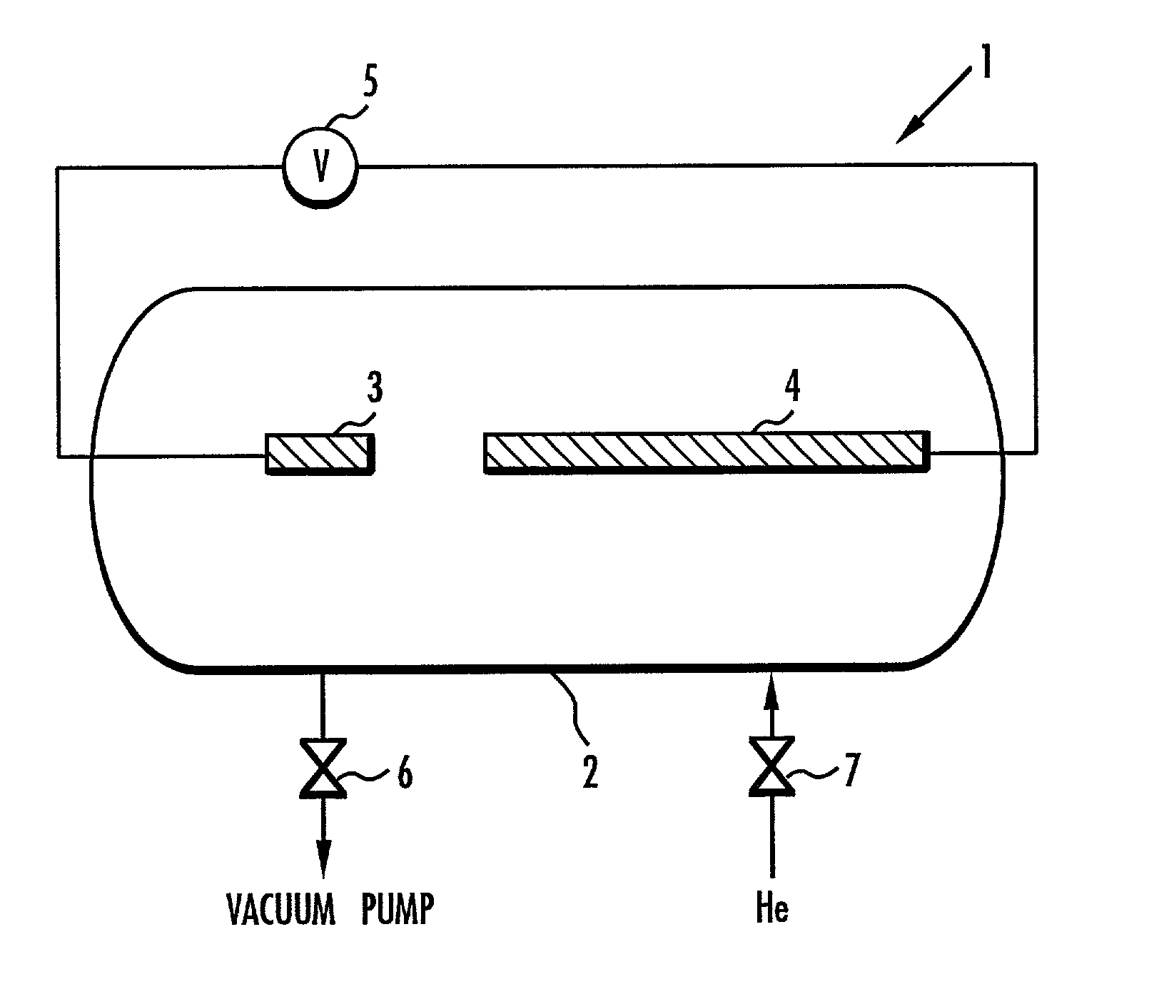
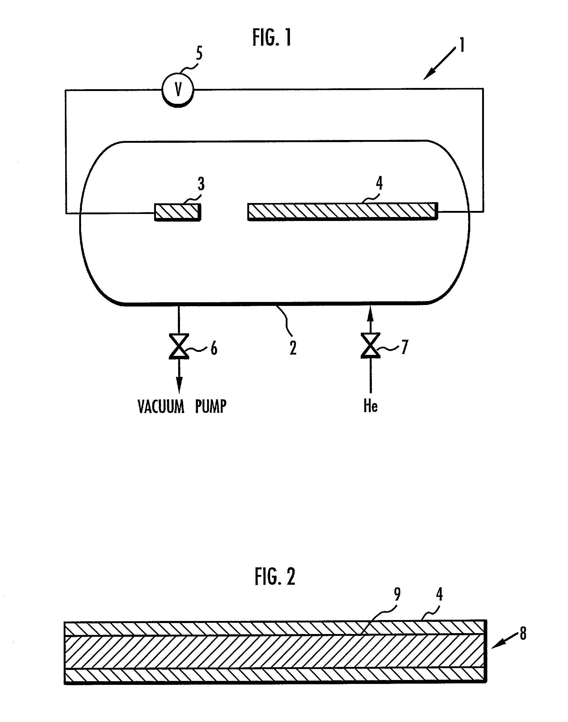
[0044] First, a hollow cylindrical, highly pure graphite rod having an outside diameter of 6 mm, an inside diameter of 3 mm, and a length of 150 mm was prepared. Then, the hollow space in the graphite rod was filled with a mixed catalyst which has been mixed in advance, producing the positive electrode 4 shown in FIG. 1. The mixed catalyst was a mixture of powders of Ni and Y as the main catalyst, a powder of Ti as the auxiliary catalyst, and a powder of graphite. The mixed catalyst was prepared to mix the constituents at ratios of Ni:Y:Ti:C=2:2:2:94 (atom number ratios) with respect to the total amount of the positive electrode. The total weight (initial weight) of the positive electrode 4 was 7.8 g.

[0045] Then, the negative electrode 3 in the form of a solid cylindrical, highly pure graphite rod and the positive electrode 4 were installed in the arc discharging system 1 shown in FIG. 1, and then the arc discharging chamber 2 was closed. The on / off valve 6 was opened to evacuate t...


PUM

PropertyMeasurementUnit
Percent by massaaaaaaaaaa
Percent by atomaaaaaaaaaa
Fractionaaaaaaaaaa

Abstract

There is provided a method of manufacturing a carbon nanotube so as to be able to increase the yield of a web and to increase the amount of a carbon nanotube contained in the web. A high-energy heat source is caused to act on carbon in the presence of catalysts. The catalysts include a main catalyst made of at least one metal which is selected from the group consisting of an iron group element, a platinum group element, and a rare earth element, and an auxiliary catalyst made of a material which causes an exothermic reaction in a process of generating the web including the carbon nanotube. The auxiliary catalyst is made of a material for generating a carbide more stable in terms of thermal energy than a carbide generated by the main catalyst. The free formation energy of the carbide generated from the material is smaller than the free formation energy of the carbide generated by the main catalyst. The main catalyst is made of at least one metal which is selected from the group consisting of Fe, Co, Ni, Rh, Ru, Pd, Pt, Y, La, and Ce. The auxiliary catalyst is made of at least one material selected from the group consisting of Ti, Zr, Hf, V, Nb, Ta, Cr, Mo, W, B, Al, and Si. Typically the main catalyst is made of Ni-Y, and the auxiliary catalyst is made of Ti.

Description

[0001] 1. Field of the Invention[0002] The present invention relates to a method of manufacturing a carbon nanotube.[0003] 2. Description of the Related Art[0004] Heretofore, it is known in the art that a web as an intermediate product including a carbon nanotube is produced by causing a metal catalyst to act on a carbon vapor in a high temperature atmosphere. The web usually includes a carbon nanotube, which is desired to be obtained, amorphous carbon, and a residual catalyst. The web is subsequently highly purified to obtain the carbon nanotube.[0005] If a sufficiently high temperature is not achieved when the metal catalyst acts on the carbon vapor, the amount of amorphous carbon, which is considered to be an impurity, is increased. Therefore, a laser, a plasma, an arc discharge, or the like is used as a high-energy heat source for producing the high temperature atmosphere.[0006] The metal catalyst is made of iron (Fe), cobalt (Co), and nickel (Ni), which are iron-group elements,...

Claims


Application Information

Patent Timeline
IPC IPC(8): B82B3/00B01J23/10B01J23/46B01J23/63B01J23/755B01J23/76B01J23/847B01J23/86C01B31/02
CPCB82Y30/00B82Y40/00C01B31/0233C01B32/162
Inventor GOTO, HAJIMEFURUTA, TERUMITOKUNE, TOSHIOFUJIWARA, YOSHIYAOHASHI, TOSHIYUKI
Owner HONDA MOTOR CO LTD
Why Eureka
Try Eureka