[0005] According to another aspect of the present invention, there is provided an apparatus for mixing
compressed air with fuel, comprising a body having a mixing channel for mixing fuel and air, a primary fuel inlet and a secondary fuel inlet, wherein the secondary fuel inlet is adapted to admit fuel into a zone of separated flow on the body. In a further aspect of the present invention, the secondary fuel inlet is positioned outside of the mixing channel. The
advantage of this is that a relatively small amount of fuel may be admitted to a zone in which there is little mixing of air and fuel, therefore providing flame stability and avoiding flame blow-out, whilst the majority of fuel is admitted through a primary fuel inlet in the mixing channel to produce a well mixed mixture of air and fuel.
[0009] Preferably, the mixing channel comprises a bore formed in the body of the apparatus, the bore having an elliptical cross section, which may be circular. The
advantage of an elliptic cross section channel is that fuel may be conveniently admitted into the channel from around the channel, so as to increase mixing of the fuel with air entering the channel, and so the channel flow does not suffer from the reduced effect of area that can occur in the corners of rectangular channel flows.
[0010] Preferably, the zone of separated flow is outside of the mixing channel so as to avoid reducing the mixing channel effective area. The secondary fuel inlet is more preferably positioned downstream of the mixing channel. The
advantage of this is that air and fuel are well mixed prior to secondary fuel being added, thus minimising NOx emissions, and yet the
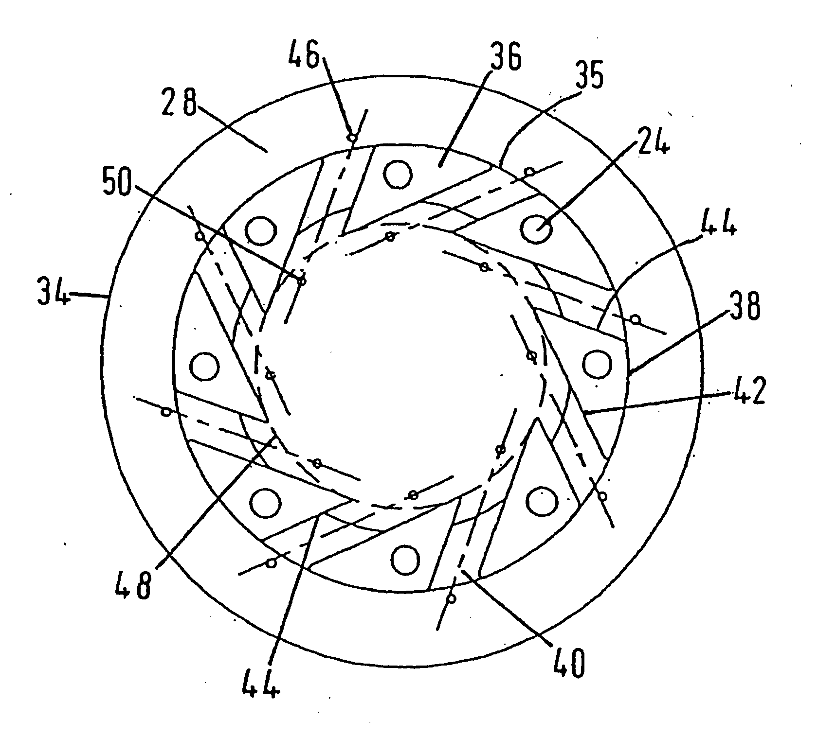
pilot (or secondary) fuel is available when the mixture is vulnerable to flame blow-out. The body may be a swirler. The mixing channels may be equi-spaced around the circumference of the swirler, and the secondary fuel inlets may be equi-spaced around the center of the swirler to facilitate good mixing of air and fuel. In other cases, the secondary fuel inlets may not be equally spaced. Preferably, the secondary fuel inlets are positioned on axes, each axis being aligned with the longitudinal axis of a mixing channel. Hence, fuel may be admitted into multiple streams of air and the mixture is able to enter the air / fuel chamber from several directions simultaneously, creating a circumferentially uniform influx of the mixture into the air / fuel chamber. In one aspect of the invention, there may be an equal number of secondary fuel inlets and primary fuel inlets, and in another aspect of the invention, there may be fewer secondary fuel inlets than there are primary fuel inlets. Preferably, the mixing channels are oriented so as to impart a swirl component of motion to the air / fuel mixture exiting the mixing channels, such that a vortex is formed in the air / fuel chamber producing a low pressure core in the air / fuel chamber flow. The low-pressure core will induce mixture in the air / fuel chamber to recirculate back up the chamber such that any excess fuel in the mixture can be burnt.
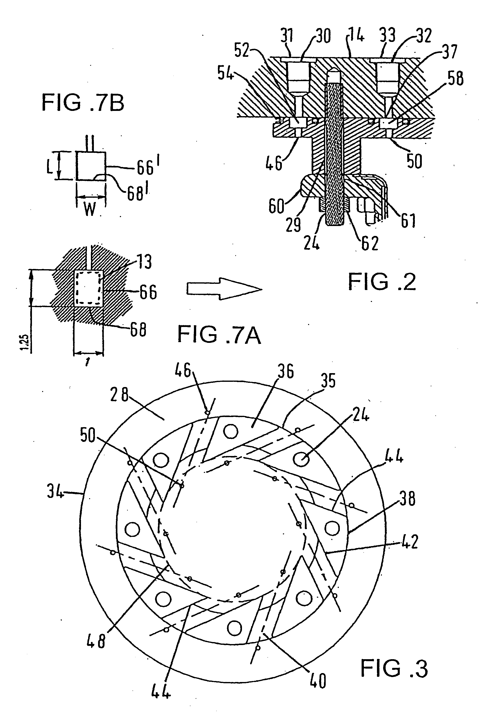
[0011] The removable means for metering of the fuel preferably comprises a fuel-metering insert. An advantage of a removable fuel metering means is that the means may be calibrated outside of the apparatus and then installed on the apparatus. This is not only more convenient for the calibrator, but also avoids having to stop the apparatus in order to perform the task, reducing costly
downtime. Preferably, the fuel-metering insert comprises a
bell mouth entrance and a main insert bore, the
bell mouth reducing pressure losses as intake air enters the insert. Preferably, the fuel-metering insert is insertable into the mixing channel insert bore and may be threadably insertable (or a push fit) into the mixing channel insert bore for ease of installation and removal thereof.
[0012] When installed onto the apparatus, the insert's bell-mouth entrance may define the mixing channel entrance. Preferably, when the insert is installed on the apparatus, the mixing channel then comprises the
bell mouth entrance through which mixing air enters the insert, the main insert bore, the body channel main bore and exit. Preferably, the mixing channel body bore has a cross section graduating from being elliptical adjacent the mixing channel insert bore to rectangular at the exit, such that the flow exiting the mixing channel is tangential to the body, producing a uniform vortex in the air / fuel chamber. The insert's main bore may comprise an elliptical cross section having a similar cross section to that of the mixing channel body bore, thus ensuring a smooth transition between the two bore sections. This will allow the air / fuel mixture to flow undisturbed to the channel exit. The elliptical cross section is preferably a circular cross section to obtain the advantage already mentioned.
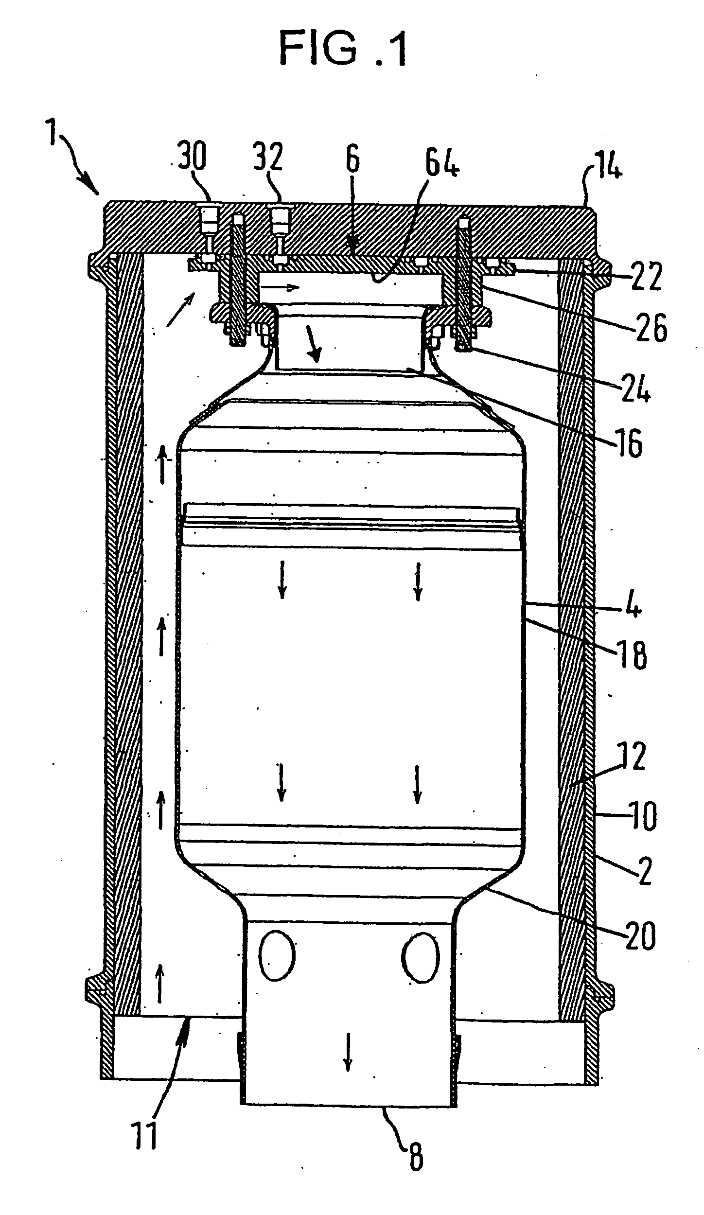
[0017] In a preferred construction, an
improved method of
fuel injection for a lean, well-mixed
system for use in a low NOx combustor is provided in combination with a radial inflow swirler / mixing apparatus, employed for establishing a flame stabilizing zone. A preferably movable fuel
injector or plug gives advantages over conventional methods in terms of mixing length, flow prediction, ease of calibration, clean
aerodynamics and pressure loss. The
injector / removable plug / portion of the mixing apparatus is essentially a bell-mouthed air metering orifice of high
discharge coefficient, which preferably screws or push-fits into the body of the swirler / mixing apparatus which is preferably of the radial inflow type. The
injector is preferably surrounded by a gas fuel gallery from which the fuel is injected into the mixing channel through one or more fuel metering holes. The size and number of the holes may be selected to control the quantity of fuel injected. Mixing of fuel and air may be achieved in a relatively
short distance from the point of injection. In contrast, other conventional injection systems are believed to incorporate stub tubes and wall injectors needing long passage lengths to achieve low standard deviation of mixing and low NOx production in the subsequent flame zone. In addition, these known injectors often upset the
aerodynamics and
discharge coefficient of the mixing channel, calling for individual calibration and higher pressure losses. Additional benefits from improved injection / mixing of fuel may be the option of selecting a lower combustion zone
airflow and therefore wider flame
stability margin at a given level of NOx production and the benefit of such a change may be the allocation of more air for cooling other parts of a combustor on which the mixing apparatus may be employed.

