Receiver system

a receiver and receiver technology, applied in the field of receiver systems, can solve the problems of unsatisfactory gain characteristics of individual filter circuits, inability to reduce the variation of cutoff frequencies, and inability to offer satisfactory reception performan

Inactive Publication Date: 2006-11-16
ROHM CO LTD
View PDF9 Cites 4 Cited by
  • Summary
  • Abstract
  • Description
  • Claims
  • Application Information

AI Technical Summary

Benefits of technology

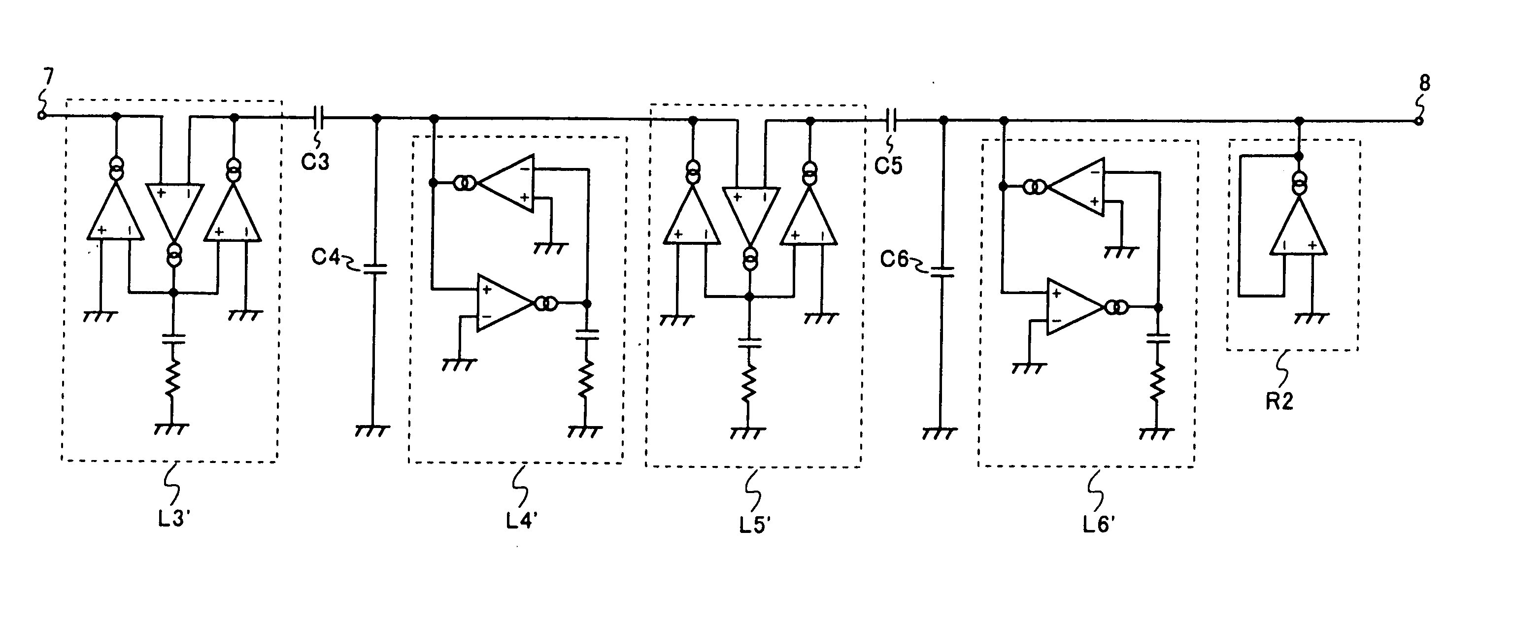
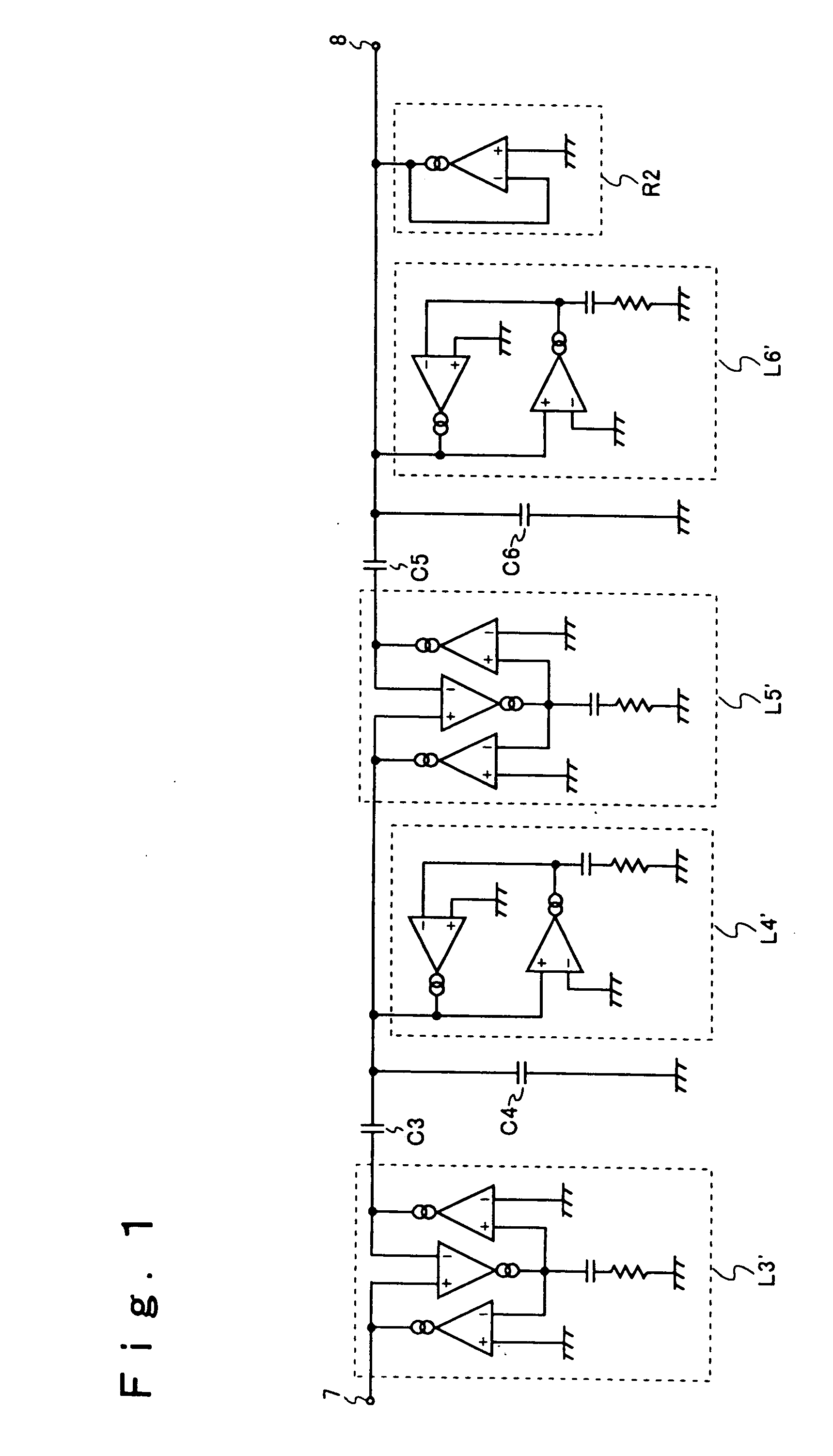
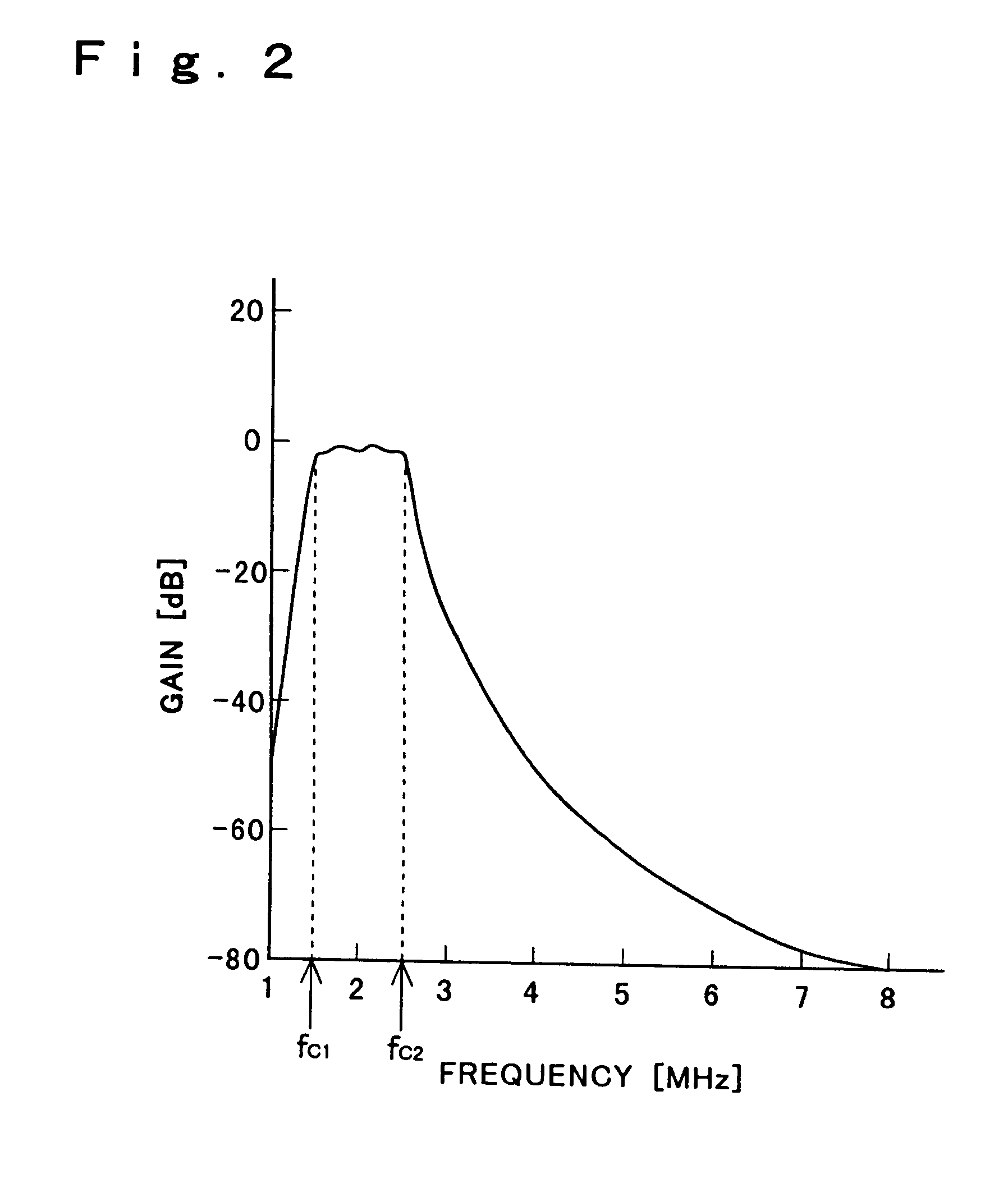
[0027] According to another aspect of the present invention, a receiver system is provided with: an antenna for receiving a high-frequency signal; an amplifier for amplifying the high-frequency signal output from the antenna; a local oscillator for producing a local oscillation signal; a mixer for mixing the output signal of the amplifier and the local oscillation signal to produce an intermediate signal; and a band-pass filter circuit for eliminating unnecessary frequency components from the output signal of the mixer. The band-pass filter circuit is composed of a low-pass filter that receives the output signal of the mixer and a band-pass filter that receives the output signal of the low-pass filter. Here, the value obtained by dividing the higher cutoff frequency of the band-pass filter by the lower cutoff frequency thereof is smaller than 2, the center frequency of the band-pass filter is within a range of from about 1 to 3 MHz, and the cutoff frequency of the low-pass filter is higher than the center frequency of the band-pass filter.

Problems solved by technology

The presence of such negative resistance leads to oscillation.
A receiver system, when provided with a band-pass filter circuit with such inadequate gain characteristics, does not offer satisfactory reception performance.
This makes it impossible to reduce variations in the cutoff frequencies, which are determined by those circuit constants.
Thus, the individual filter circuits have unsatisfactory gain characteristics, and produce great errors in the actually obtained cutoff frequencies from their design values.
However, the gm band-pass filter of FIG. 17 includes active elements (transistors) inside the operational transconductance amplifiers, and thus suffers from distortion in the input-output characteristics.
This distortion causes intermodulation.
Moreover, here, the third-order input intercept point IIP3′ is not expected to be improved by the adjustment of the circuit constants.
A receiver system, when provided with a gm band-pass filter with too low a value of the third-order input intercept point IIP3′, does not offer satisfactory reception performance.

Method used


Image

  • Receiver system
  • Receiver system
  • Receiver system

Examples


Embodiment Construction

[0051] Hereinafter, embodiments of the present invention will be described with reference to the drawings. First, the equivalent inductor circuits employed in a filter circuit embodying the invention will be described with reference to FIGS. 7 and 8.

[0052]FIG. 7 shows the configuration of an equivalent inductor circuit L1′ equivalent to an inductor having one end grounded (see FIG. 13A). It is to be noted that such circuit elements as are found also in FIG. 13B are identified with the same reference numerals and symbols, and their explanations will be omitted. The equivalent inductor circuit L1′ differs from the equivalent inductor circuit L1 in that the former is additionally provided with a resistor R3 connected in series with the capacitor C1. That is, the end of the capacitor C1 that is not connected to the OTA is grounded through the resistor R3.

[0053] Here, direct-current voltage sources may be provided individually between the non-inverting input terminal of the OTA 1 and g...


PUM


Abstract

A conventional receiver system has a filter circuit with unsatisfactory gain characteristics, and thus does not offer satisfactory reception performance. A receiver system of the invention has a filter circuit employing an equivalent inductor circuit including a capacitor, a gyrator composed of a plurality of operational transconductance amplifiers and having the capacitor as a load, and a resistor connected in series with the capacitor. A conventional receiver system has a band-pass filter circuit with a low third-order input intercept point, and thus does not offer satisfactory reception performance. The receiver system of the invention has, in the stage following a mixer, a band-pass filter circuit composed of a low-pass filter and a band-pass filter receiving the output signal of the low-pass filter, wherein the value obtained by dividing the higher cutoff frequency of the band-pass filter by the lower cutoff frequency thereof is smaller than 2, the center frequency of the band-pass filter is within a range of from about 1 to 3 MHz, and the cutoff frequency of the low-pass filter is higher than the center frequency of the band-pass filter.

Description

BACKGROUND OF THE INVENTION [0001] 1. Field of the Invention [0002] The present invention relates to a receiver system. More particularly, the present invention relates to a receiver system provided with a filter circuit employing an operational transconductance amplifier. [0003] 2. Description of the Prior Art [0004] A receiver system is usually provided with a filter circuit in the form of an integrated circuit. When a filter circuit including an inductor is formed into an integrated circuit, since the inductor is difficult to integrate, it is customary to use, instead of an inductor having one end grounded as shown in FIG. 13A, an equivalent inductor circuit L1 as shown in FIG. 13B and, instead of a floating inductor as shown in FIG. 14A, an equivalent inductor circuit L2 as shown in FIG. 14B. [0005] The equivalent inductor circuit L1 of FIG. 13B is composed of operational transconductance amplifiers (hereinafter referred to as OTAs) 1 and 2 and a capacitor C1. The output termina...

Claims


Application Information

Patent Timeline
Patent Type & Authority Applications(United States)
IPC IPC(8): H04B1/28H04B1/16H04B1/10H04B1/12
CPCH04B1/12H04B1/1036H03H11/0444H03H11/486
Inventor SHIMADA, YOSHIKAZUASHIDA, HIROYUKI
Owner ROHM CO LTD
Why Eureka
Try Eureka