
Neuro thrombectomy catheter

a catheter and thrombosis technology, applied in the field of thrombosis or atherectomy devices, can solve the problems of limiting the utility of the device, affecting the use of the device, and the length of the portion excised at each pass of the atherectomy blade is necessarily limited to the length of the cavity in the device, so as to achieve sufficient kink resistance and pushability, and small outside diameter

Inactive Publication Date: 2006-11-16
TYCO HEALTHCARE GRP LP
View PDF99 Cites 69 Cited by
  • Summary
  • Abstract
  • Description
  • Claims
  • Application Information

AI Technical Summary

Benefits of technology

[0010] There is provided in accordance with one aspect of the present invention a neurothrombectomy catheter adapted to access remote intracranial vasculature. The thrombectomy catheter comprises an elongate flexible tubular body having a sufficiently small outside diameter and sufficient kink resistance and pushability to navigate through the common carotid artery, the internal carotid artery, and at least as far distal as the M2, or sylvian, segment of the middle cerebral artery. Rotation of a cutter tip in a distal portion of the catheter, and application of vacuum through the catheter, enables removal of thrombus from the vicinity of the bifurcation in the distal M1 segment of the middle cerebral artery, or other remote location elsewhere in the intracranial, coronary, or other vasculature of a patient.

Problems solved by technology

If left untreated, such stenoses can so sufficiently reduce perfusion that angina, hypertension, myocardial infarction, strokes and the like may result.
While such devices provide for directional control in selection of tissue to be excised, the length of the portion excised at each pass of the atherectomy blade is necessarily limited to the length of the cavity in the device.
The length and relative rigidity of the housing limits the maneuverability and therefore also limits the utility of the device in narrow and tortuous arteries such as coronary arteries.
Such devices are also generally limited to lateral cutting relative to the longitudinal axis of the device.
However, not all atherosclerotic plaques, and certainly not all thrombi, are hardened and calcified.
Thus, one cannot always rely entirely on the differential cutting properties of such abrasives to remove atherosclerotic material from an arterial wall, particularly where one is attempting to remove all or almost all of the atherosclerotic material.
Indeed, lateral pressure by such healthy tissue against the abrading device is inherently required to keep the abrading device in contact with the remaining stenotic tissue on the opposite wall of the passageway.
Under these conditions, a certain amount of damage to the healthy tissue is almost unavoidable, even though undesirable, and there is a clear risk of perforation or proliferative healing response.
In some cases, the “healthy tissue” across from a stenotic lesion may be somewhat hardened by the interaction (i.e., it has diminished elasticity); under such circumstances, the differential cutting phenomenon described by Auth will also be diminished, resulting in a risk that this “healthy” tissue may also be removed, potentially causing perforation.
Additional, unique challenges are encountered in the design of a rotational atherectomy or thrombectomy catheter which is intended to access the remote coronary arteries or the intracranial vasculature.
For example, the prior art catheters generally are either too large in diameter to access remote vasculature, or insufficiently flexible, particularly at the distal, cutting tip, to navigate tortuous vasculature.

Method used


Image

  • Neuro thrombectomy catheter
  • Neuro thrombectomy catheter
  • Neuro thrombectomy catheter

Examples


Embodiment Construction

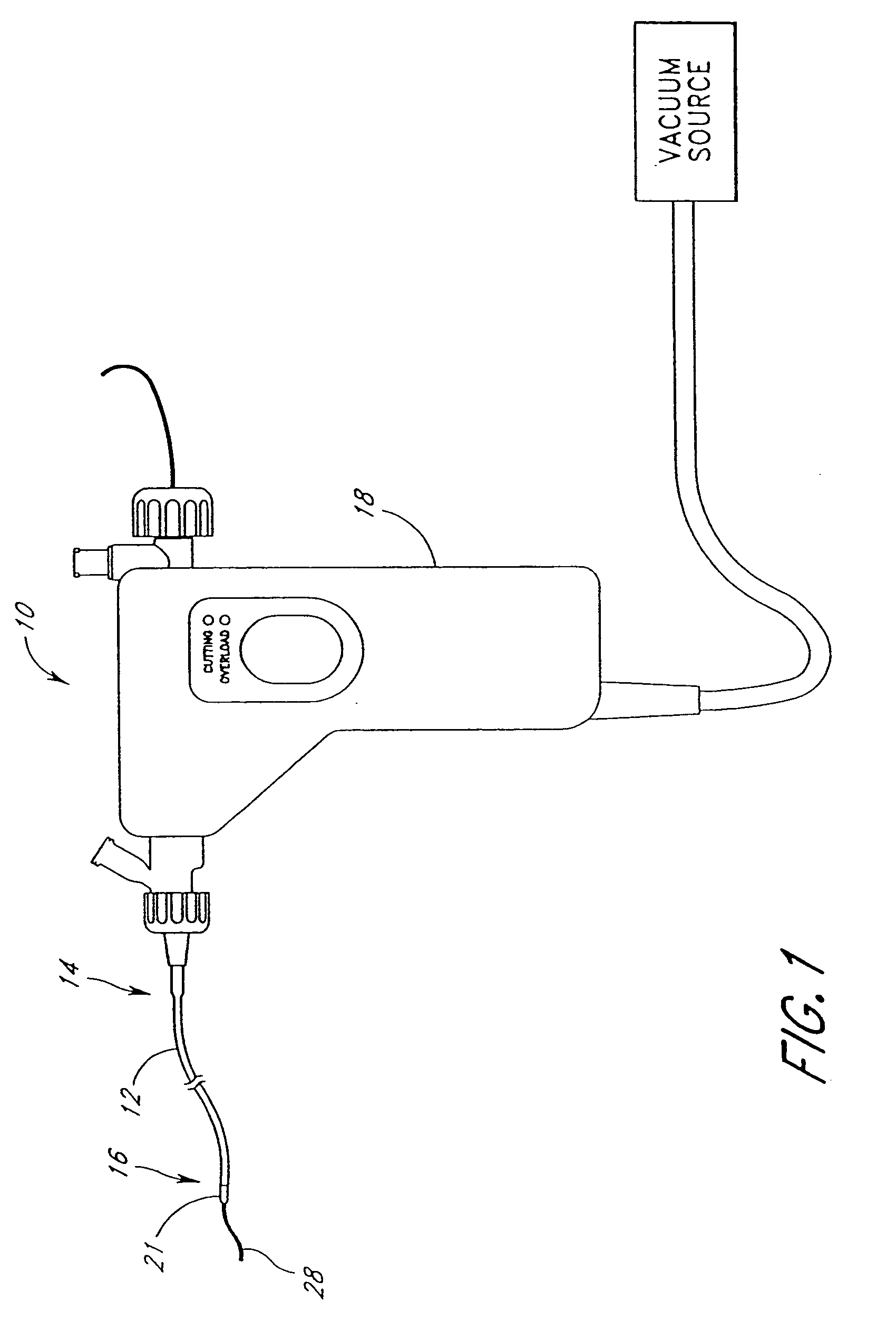
[0049] With reference initially to FIG. 1, a surgical instrument, indicated generally by reference numeral 10 having features, aspects and advantages in accordance with the present invention is depicted therein. In general, the illustrative surgical instrument comprises an elongate flexible tubular body 12 having a proximal end 14 and a distal end 16. A control 18 is preferably provided at or near the proximal end 14 of the tubular body 12 for permitting manipulation of the instrument 10. The control 18 advantageously carries electronic controls and indicators as well as vacuum controls as will be discussed below.

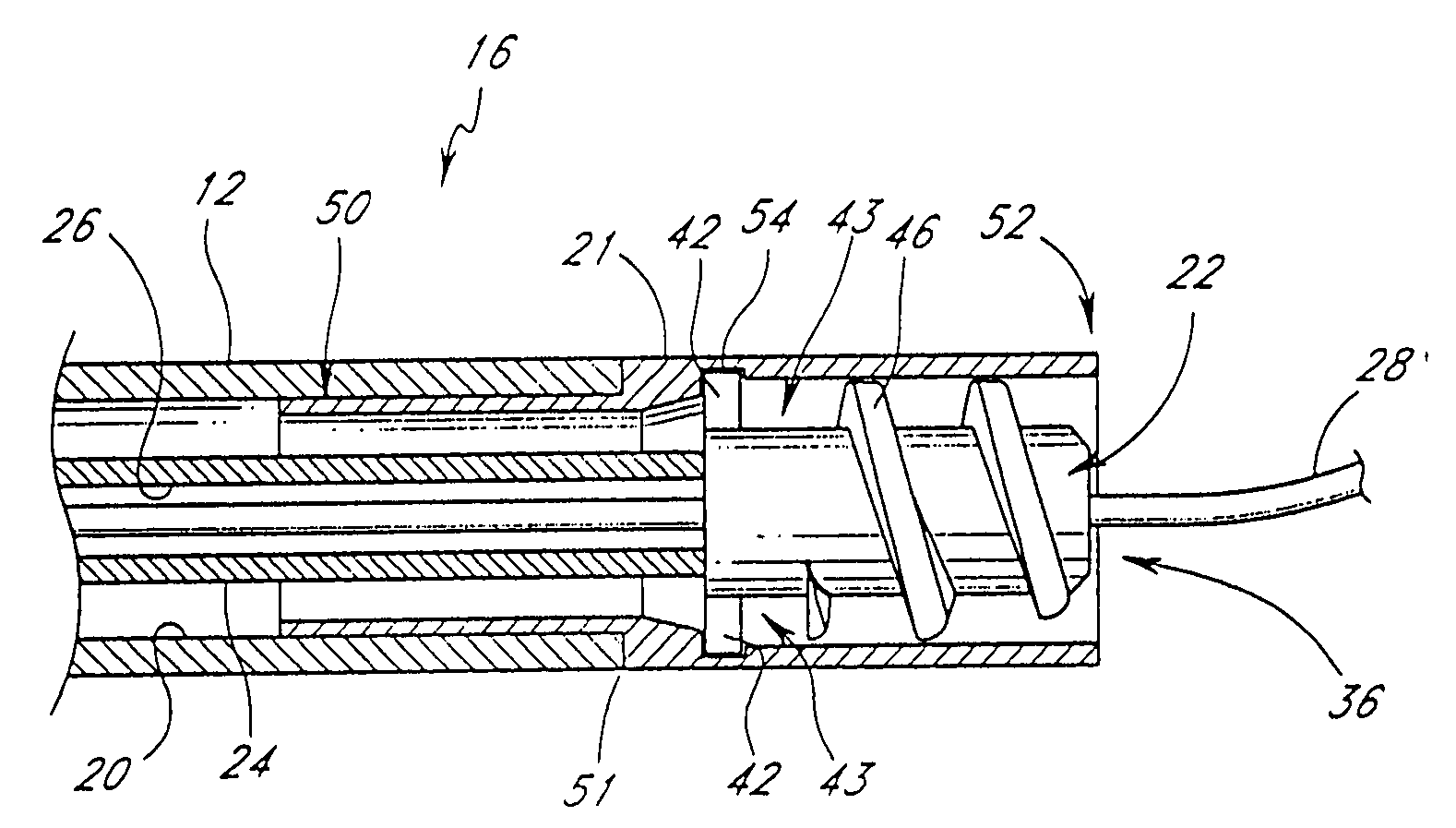
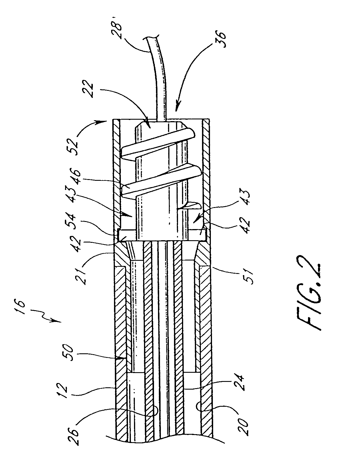
[0050] With reference now to the partially sectioned view of FIG. 2, the tubular body 12 preferably has an elongate central lumen 20. Desirably, the tubular body 12 has a cutter housing 21 for receiving a cutter 22 that may rotate therein. The illustrated cutter 22 is coupled to the control 18 for rotation by way of an elongate flexible drive shaft 24, as will be described...


PUM


Abstract

An elongate tubular body extends between a rotatable cutter and a control. The cutter is connected to the control with a rotatable element. A vacuum is applied through an annular passage defined between the tubular body and the rotatable element. The tubular body has a sufficiently small outside diameter and sufficient kink resistance and pushability to navigate through arteries such as the internal carotid artery.

Description

CROSS REFERENCE TO RELATED APPLICATIONS [0001] This application is a continuation of U.S. patent application Ser. No. 10 / 200,475, filed Jul. 19, 2002, which is a continuation of U.S. patent application Ser. No. 09 / 656,635, filed Sep. 7, 2000, now U.S. Pat. No. 6,482,217, which is a continuation-in-part of U.S. patent application Ser. No. 09 / 398,241, filed Sep. 17, 1999, now U.S. Pat. No. 6,666,874, which is a continuation-in-part of U.S. patent application Ser. No. 09 / 260,199, filed on Mar. 1, 1999, now U.S. Pat. No. 6,206,898, which is a continuation-in-part of U.S. patent application Ser. No. 09 / 058,513, filed on Apr. 10, 1998, now U.S. Pat. No. 6,001,112.BACKGROUND OF THE INVENTION [0002] The present invention generally relates to thrombectomy or atherectomy devices and, more particularly, to thrombectomy catheter devices adapted to access vasculature above the carotid arteries. [0003] A variety of techniques and instruments have been developed to remove obstructive material in a...

Claims


Application Information

Patent Timeline
IPC IPC(8): A61B17/22A61B17/00A61B17/32
CPCA61B17/320758A61B2017/00022A61B2017/00685A61B2017/22039A61B2017/22052A61B2017/320775A61B2017/22071A61B2017/320004A61B2017/320008A61B2017/320032A61B2017/22068
Inventor PINTOR, RAFAELCULBERT, BRADLEY STEVENHEITZMANN, HAROLD ALEXANDERSTAMBAUGH, BRUCE D.
Owner TYCO HEALTHCARE GRP LP
Learn More