Method and apparatus for vacuum-assisted light-based treatments of the skin

a technology vacuum-assisted light-based treatment, which is applied in the field of light-based skin treatment, can solve the problems of inability to tolerate prior art wide-area tattoo removal, ineffective apparatus, and inability to penetrate deep into the skin. , to achieve the effect of facilitating and facilitating the penetration of light-based treatmen

Inactive Publication Date: 2006-11-16
CANDELA CORP
View PDF79 Cites 367 Cited by
  • Summary
  • Abstract
  • Description
  • Claims
  • Application Information

AI Technical Summary

Benefits of technology

[0041] The present invention is directed to apparatus for vacuum-assisted light-based skin treatments. The apparatus comprises a vacuum chamber which is transparent or translucent to intense pulsed monochromatic or non-coherent light directed to a skin target. A vacuum is applied to said vacuum chamber, whereby said skin target is drawn to said vacuum chamber. The efficacy and utility of the apparatus are achieved by employing the apparatus in two modes: (a) in a vacuum applying mode wherein a high vacuum level ranging from 0-1 atmoshpheres is attained and (b) in a vacuum release mode upon deactivation of the light source and of the vacuum pump after optical energy associated with the directed light has been absorbed within a predetermined depth under the skin surface, wherein atmospheric air is introduced to the vacuum chamber so that the vaccum chamber may be speedily repositioned to another skin target.

Problems solved by technology

Melanin and blood in the skin normally do not allow light at these wavelengths to penetrate deep into the skin due to strong absorption.
Prior art wide-area tattoo removal is generally not tolerable and requires the application of a topical analgesic cream such as EMLA which is risky when applied over larger areas.
When red tattoos are removed with green laser or IPL light according to prior art methods, blood vessels present in the skin are thermally damaged since red blood vessels absorb green light.
The thermal damage often results in bruises which last a few days.
A vacuum chamber which is excessively small, e.g. 5×5 mm, may not efficiently inhibit pain transmission.

Method used


Image

  • Method and apparatus for vacuum-assisted light-based treatments of the skin
  • Method and apparatus for vacuum-assisted light-based treatments of the skin
  • Method and apparatus for vacuum-assisted light-based treatments of the skin

Examples


example 1

[0407] An experiment was performed to determine the time response of skin erythema following application of a vacuum onto various skin locations. A pipe of 6 mm diameter was sequentially placed on a hand, eye periphery, arm, and forehead at a subatmospheric pressure of aproximately 100 millibar. The skin locations were selected based on the suitability for treatment: the hands and eye periphery for wrinkle removal, arm for hair removal, and forehead for port wine stain treatment. The vacuum was applied for the different periods of time of 1 / 10, ½, 1, 2, 3 seconds and then stopped. The erythema level and erythema delay time were then measured.

[0408] The response time of the hand and eye periphery was ½ sec, the response time of the arm was 1 second and the response time of the forehead was ½ second. Accordingly, the experimental results indicate that the necessary delay between the application of the vacuum and firing of the laser or intensed pulsed light is preferably less than 1 s...

example 2

[0410] An intense pulsed light system comprising a broad band Xe flashlamp and a cutoff filter for limiting light transmission between 755 nm and 1200 nm is suitable for aesthetic treatments, such that light delivered through a rectangular light guide is emitted at an energy density of 20 J / cm2 and a pulse duration of 40 milliseconds, for hair removal with respect to a treated area of 15×45 mm.

[0411] While efficacy of such a light system for the smoothening of fine wrinkles, i.e. photorejuvenation, is very limited by prior art devices, due to the poor absorption of light by blood vessels at those wavelengths, enhanced light absorption in targeted skin structures in accordance with the present invention would increase the efficacy.

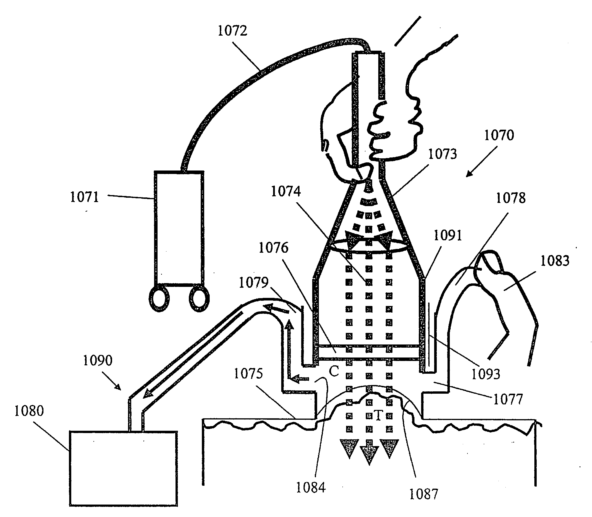
[0412] A transparent vacuum chamber of 1 mm height is preferably integrally formed with a handpiece through which intense pulsed light is directed. A diaphragm miniature pump, such as one produced by Richly Tomas which applies a vacuum level of 100 millib...

example 3

[0414] An Nd:YAG laser operating at 1064 nm, 40 milliseconds pulse duration, and energy density of 70 J / cm2 is suitable for prior art hair removal having a spot size of 7 mm. By prior art hair removal, absorption of light in the hair shaft melanin is limited, with a contributory factor in hair removal being attributed to the absorption of light by blood in the hair follicle bulb zone. Since the energy density level of 70 J / cm2 is risky to the epidermis of dark skin, it would be preferable to operate the laser at 40 J / cm2.

[0415] A vacuum chamber is preferably integrally formed with a handpiece through which intense pulsed light is directed, at a distance of 1 mm from the skin target. A vacuum is applied to the skin target for 2 seconds. The blood concentration near the follicle bulb and in the bulge at a depth of 4 and 2 mm, respectively, is increased by a factor of 2. As a result the laser is operated with the same efficacy at energy levels closer to 40 J / cm2 and is much safer.


PUM


Abstract

A method and apparatus are disclosed for enhancing the absorption of light in targeted skin structures and for the inhibition of pain transmission during light based treatments of the skin. After applying a vacuum to a vacuum chamber placed on a skin target and modulating the applied vacuum, the concentration of blood and / or blood vessels is increased within a predetermined depth below the skin surface of the skin target. Optical energy associated with light directed in a direction substantially normal to a skin surface adjoining the skin target is absorbed within the predetermined depth. The apparatus is suitable for treating vascular lesions with a reduced treatment energy density level than that of the prior art and for evacuating condensed vapors produced during the cooling of skin. The vacuum chamber may also have a skin flattening transmitting element which inhibits pain transmission upon applying a sufficiently high vacuum.

Description

[0001] This application claims priority from EP Patent Application No. 050007952.4 (filed Apr. 12, 2005) and from IL Patent Application No. 170132 (filed Aug. 4, 2005), and is a Continuation-In-Part of U.S. patent application Ser. No. 11 / 057,542 (filed Feb. 14, 2005), which claims priority from Israeli Patent Application No. 160510 (filed on Feb. 22, 2004) and is a Continuation-In-Part of U.S. patent application Ser. No. 10 / 498,382 (filed Jun. 10, 2004), which is a Continuation-In-Part of PCT / IL02 / 00635 (filed on Aug. 2, 2002), which is derived from IL 147009 (filed on Dec. 10, 2001) and from IL 150094 (filed on Jun. 6, 2002).FIELD OF THE INVENTION [0002] The present invention is related to the field of light-based skin treatments. More specifically, the invention is related to the utilization of light sources for the non-invasive treatment of skin disorders under the skin surface, whereby light is selectively absorbed by hair shafts, blood vessels, or collagen bundles, for the trea...

Claims


Application Information

Patent Timeline
Patent Type & Authority Applications(United States)
IPC IPC(8): A61N5/06A61B18/20A61H23/02A61N5/067
CPCA61B17/205A61N2007/0008A61B18/203A61B2017/00747A61B2017/00752A61B2017/306A61B2018/00005A61B2018/00291A61B2018/00452A61B2018/00458A61B2018/00476A61H7/008A61H9/005A61H9/0057A61M5/422A61M5/425A61N7/00A61B18/14
Inventor SLATKINE, MICHAEL
Owner CANDELA CORP
Why Eureka
Try Eureka