Method or apparatus for wrinkle treatment

Inactive Publication Date: 2017-02-23
AHARON OREN
View PDF6 Cites 3 Cited by
  • Summary
  • Abstract
  • Description
  • Claims
  • Application Information

AI Technical Summary

Benefits of technology

[0025]According to current absorption curves, lasers operating at the spectral range of approximately 650 nm to 750 that are not very well absorbed by blood vessels and Oxyhemoglobin, are being absorbed by melanin. Moreover, water absorption is minim

Problems solved by technology

The effects of aging on the dermal skin layer are significant in causing wrinkles and local sagging.
These changes in the scaffolding of the skin cause the skin to wrinkle and sag.
In order to penetrate and achieve high fluency at the subcutis skin layer, the needed amount of radiation at the skin level is very high, preventing such technologies to be available as over the counter devices.
Typically, irradiation technique is applied to the skin surface from above, even if the target lies beneath the skin level—this may have some adverse results to the upper skin level due to the high levels of fluence needed in order to achieve deep penetration.
Applying the light to the skin from above has some limitations such as a limited maximum power level and uncontrolled laser propagati

Method used


Image

  • Method or apparatus for wrinkle treatment
  • Method or apparatus for wrinkle treatment
  • Method or apparatus for wrinkle treatment

Examples


Embodiment Construction

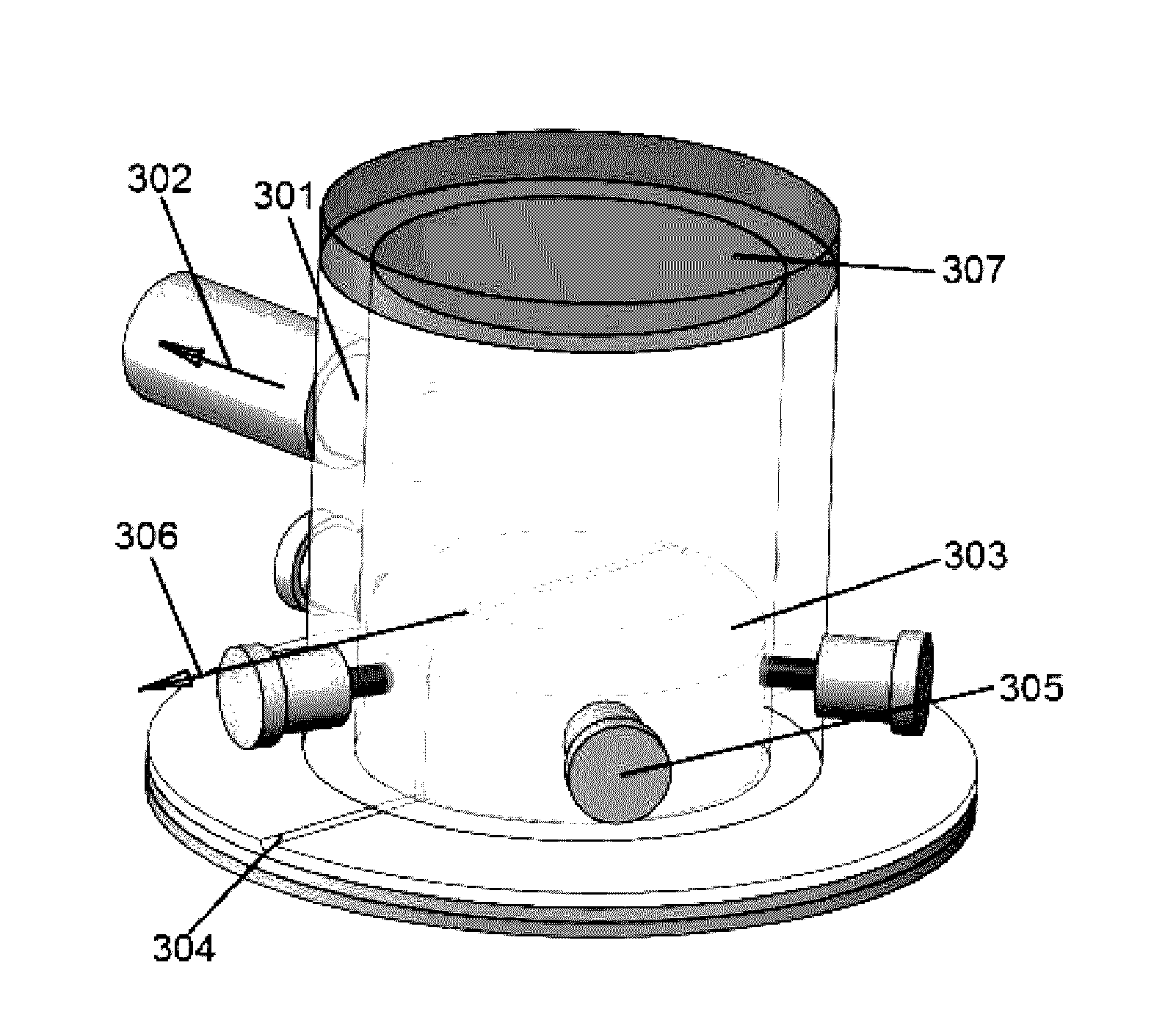
[0053]The present invention is directed towards an apparatus which is provided with a unit for lifting a preferably round shape of skin. The skin is lifted prior to the firing of multiple lasers around the raised portion. The air suction unit comprises a miniature vacuum pump and a hose through which air is evacuated from a tubular device applied to the skin and intense light passes through its wall directly to the elevated skin level. During the operation of the vacuum pump, the vacuum level within the vacuum chamber is increased and a special sensor checks vacuum level before enabling laser firing option.

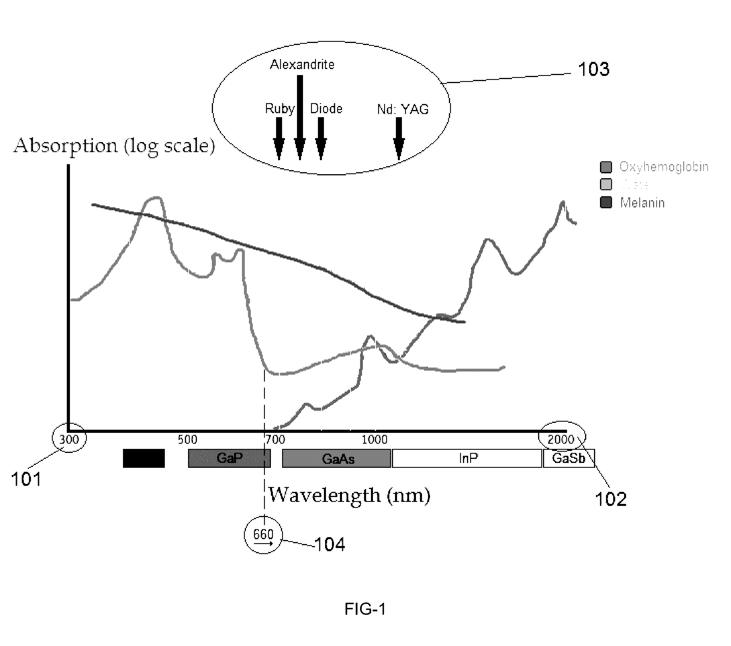
[0054]FIG. 1 illustrates the propagation of an intense pulsed laser or light beam, the wavelength of which is in the visible or near infrared region of the spectrum, i.e. shorter than 2000 nm, and longer than 300 nm and denoted as 101 and 102 respectively, popular lasers are denoted as 103 for minimizing damage to Oxyhemoglobin. A wavelength longer than 660 is a good choice and de...


PUM


Abstract

A method and apparatus are disclosed for skin wrinkle removal. After applying a tube encircling a relatively small skin area along the wrinkled line, a set of laser beams will be activated. The laser beams are mounted around the tube, pointing to its center to create a mutual point of irradiation located just below the skin's wrinkle line. Optical energy from lasers is directed to a point under the skin by radiating through the transparent tube. For ease of use, the encircled skin portion is lifted, preferably by vacuum, enabling laser radiation to penetrate under the skin from outside the lifting tube. The apparatus is suitable for treating skin wrinkles by targeting the sub skin melanin without damaging skin surface. The apparatus may also be used for other aesthetic face treatments, including disorders located around the eye. The used laser radiation is in the wavelength region of 1500 to 1800 nm, which is regarded to be eye safe. Other laser wavelength could be used, especially in the 700 nm region with confidence, since most radiation is enclosed within the skin portion on the transparent tube. The treatment energy density level on the skin penetration point is relatively low and thus not harmful to the epidermis. However, heating effect is maximized at the central point just beneath the wrinkle—which causes damage to the collagen. Later on, when healing occurs, the skin will be stretched and wrinkles will be diminished. This technology is less damaging to the skin than that of the prior and targets only the under wrinkle collagen. Statistically, most of the recent clinical trials showed a histological evidence of new collagen formation and significant improvement in facial rhytides. Direct, under the skin irradiation, as in our art, will be less damaging to the skin epidermis yielding improved overall results.

Description

BACKGROUND OF THE INVENTION[0001]1. Field of the Invention[0002]The present invention is related to the field of light-based skin treatments. More specifically, the invention is related to the utilization of light sources for wrinkle treatment. Other relevant disorders could be similarly treated by irradiating the point of interest located beneath the skin level. Radiation is applied to a lifted skin portion from its periphery through a transparent tube, causing the temperature at the center point under the skin to peak. By irradiating from multiple points around a lifted part of the skin, damage to the skin itself is relatively small, since it is applied from different points—each radiating with low level laser energy. By lifting a relatively small skin portion, the epidermis and dermis are stretched and thinned enabling better penetration to the subcutis.[0003]2. Description of the Related Art[0004]The subcutis is the innermost layer of the skin, and consists of a network of fat a...

Claims


Application Information

Patent Timeline
IPC IPC(8): A61N5/06
CPCA61N5/0616A61N2005/0626A61N2005/0649A61N2005/0663A61N2005/0659A61N2005/067A61N5/067
Inventor AHARON, OREN
Owner AHARON OREN
Why Eureka
Try Eureka