

Heart valve prosthesis and methods of manufacture and use
- Summary
- Abstract
- Description
- Claims
- Application Information
AI Technical Summary
Benefits of technology
Problems solved by technology
Method used
Image

Examples
Embodiment Construction
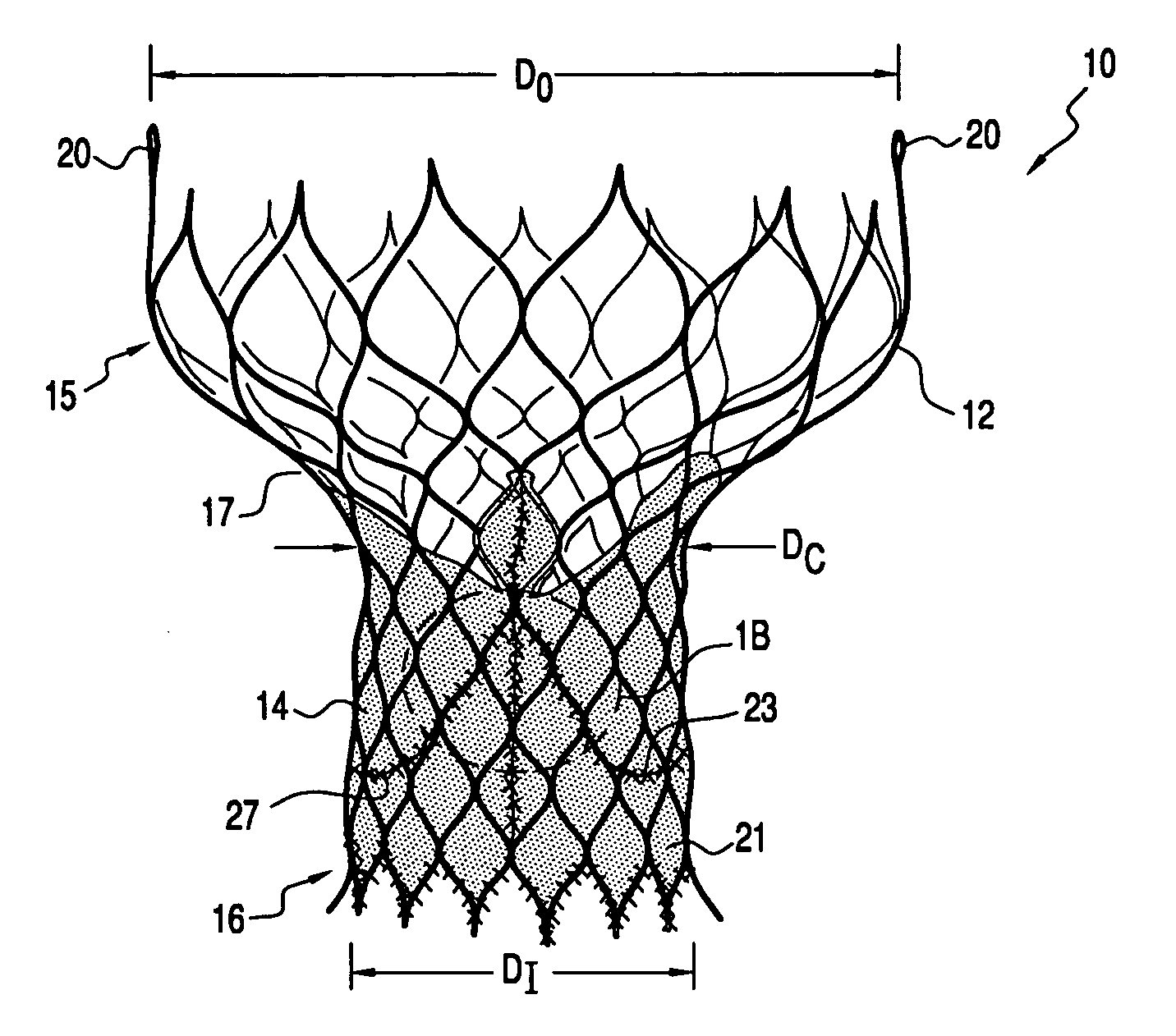
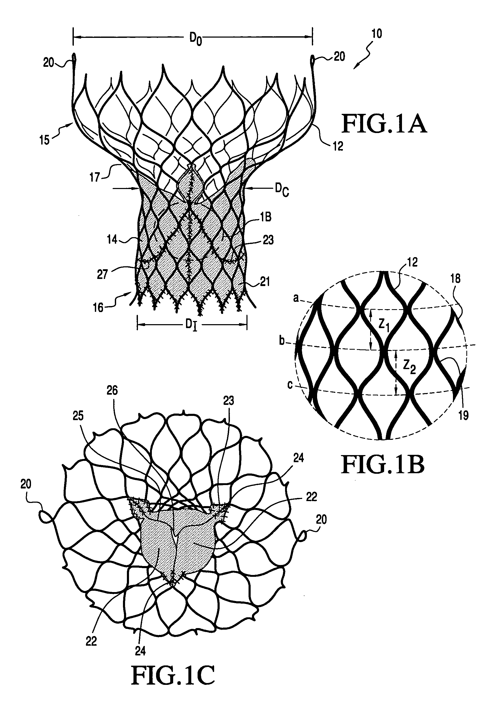
[0037] The present invention is directed to a heart valve prothesis having a self-expanding frame that supports a valve body. In a preferred embodiment, the frame has a tri-level asymmetric hourglass shape with a conical proximal section, an enlarged distal section and a constriction region having a predefined curvature when the frame is deployed. In the context of the present application, the proximal section constitutes the “inflow” portion of the valve prosthesis and is disposed in the aortic annulus of the patient's left ventricle, while the distal section constitutes the “outflow” portion of the valve prosthesis and is positioned in the patient's ascending aorta.
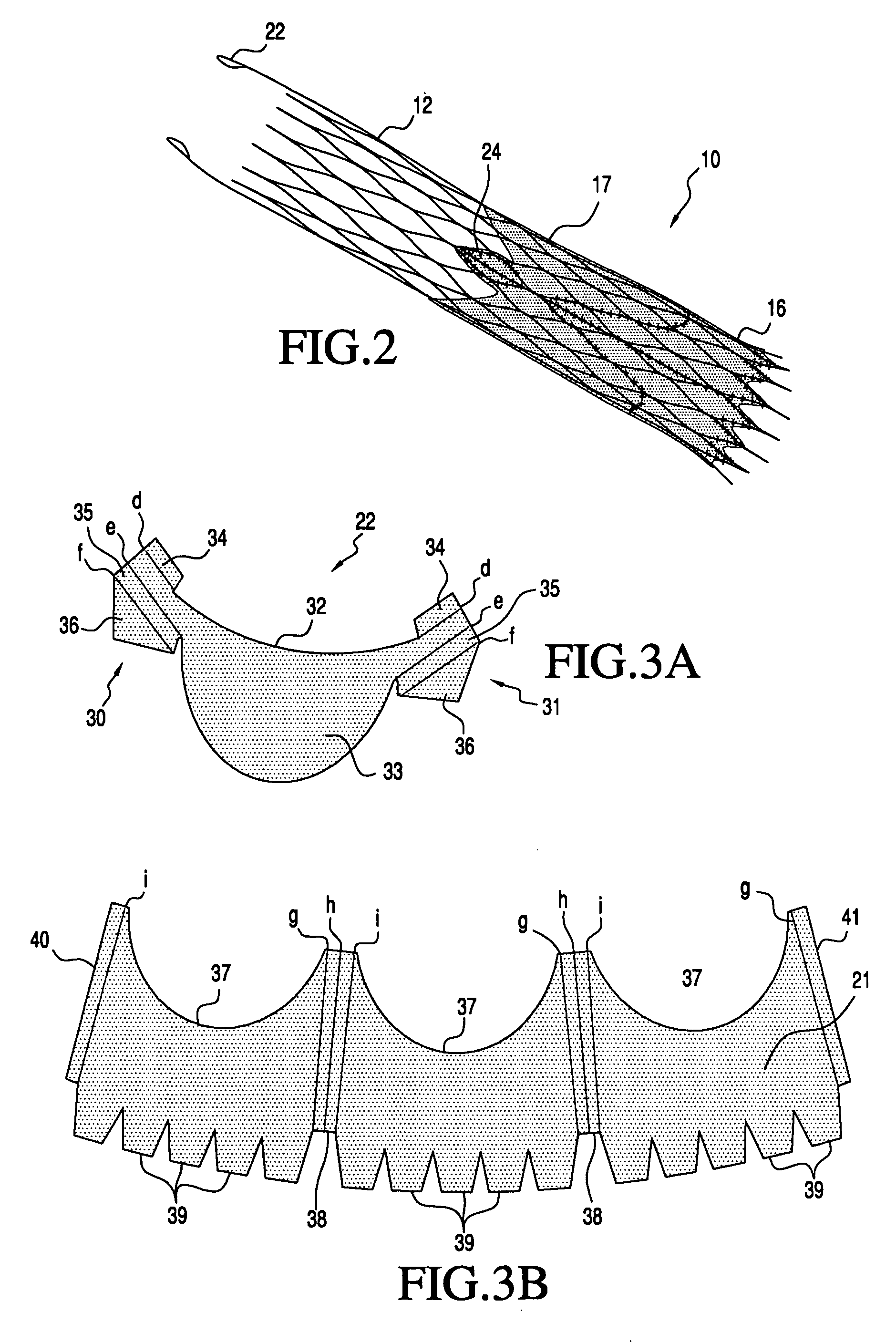
[0038] In a preferred embodiment the valve body comprises three leaflets that are fastened together at enlarged lateral end regions to form commissural joints, with the unattached edges forming the coaptation edges of the valve. The leaflets are fastened to a skirt, which is in turn affixed to the frame. The enlarged l...
PUM
 Abstract
Description
Claims
Application Information