
Embedded system self-updating method and device

a self-updating and embedded technology, applied in the field of embedded systems, can solve the problems of not fully testing software/hardware integration, still exist a few problems in the product, and still exist quite a few problems, so as to achieve the effect of reducing production costs and simplifying system design

Inactive Publication Date: 2006-11-16
ETROVISION TECH
View PDF2 Cites 37 Cited by
  • Summary
  • Abstract
  • Description
  • Claims
  • Application Information

AI Technical Summary

Benefits of technology

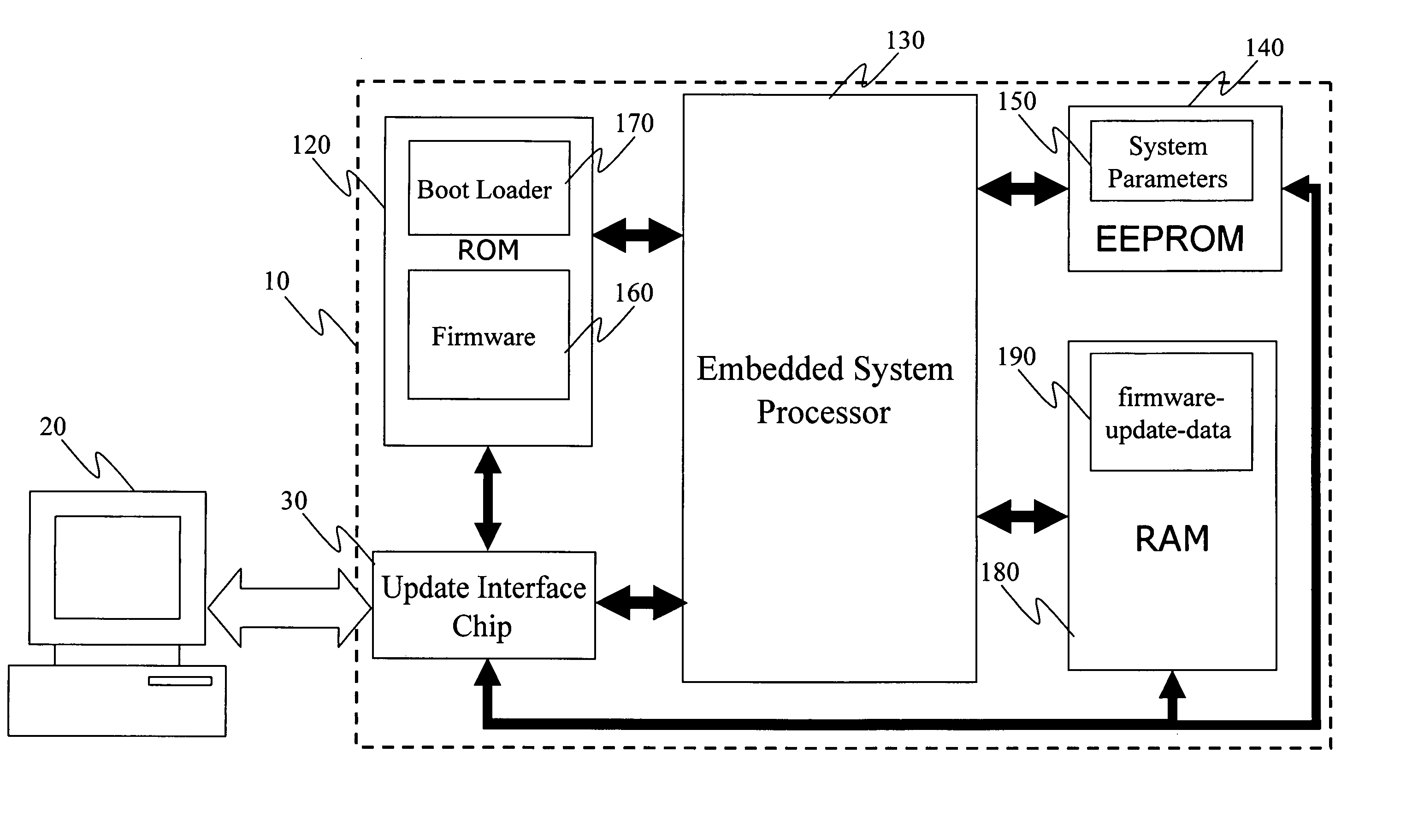
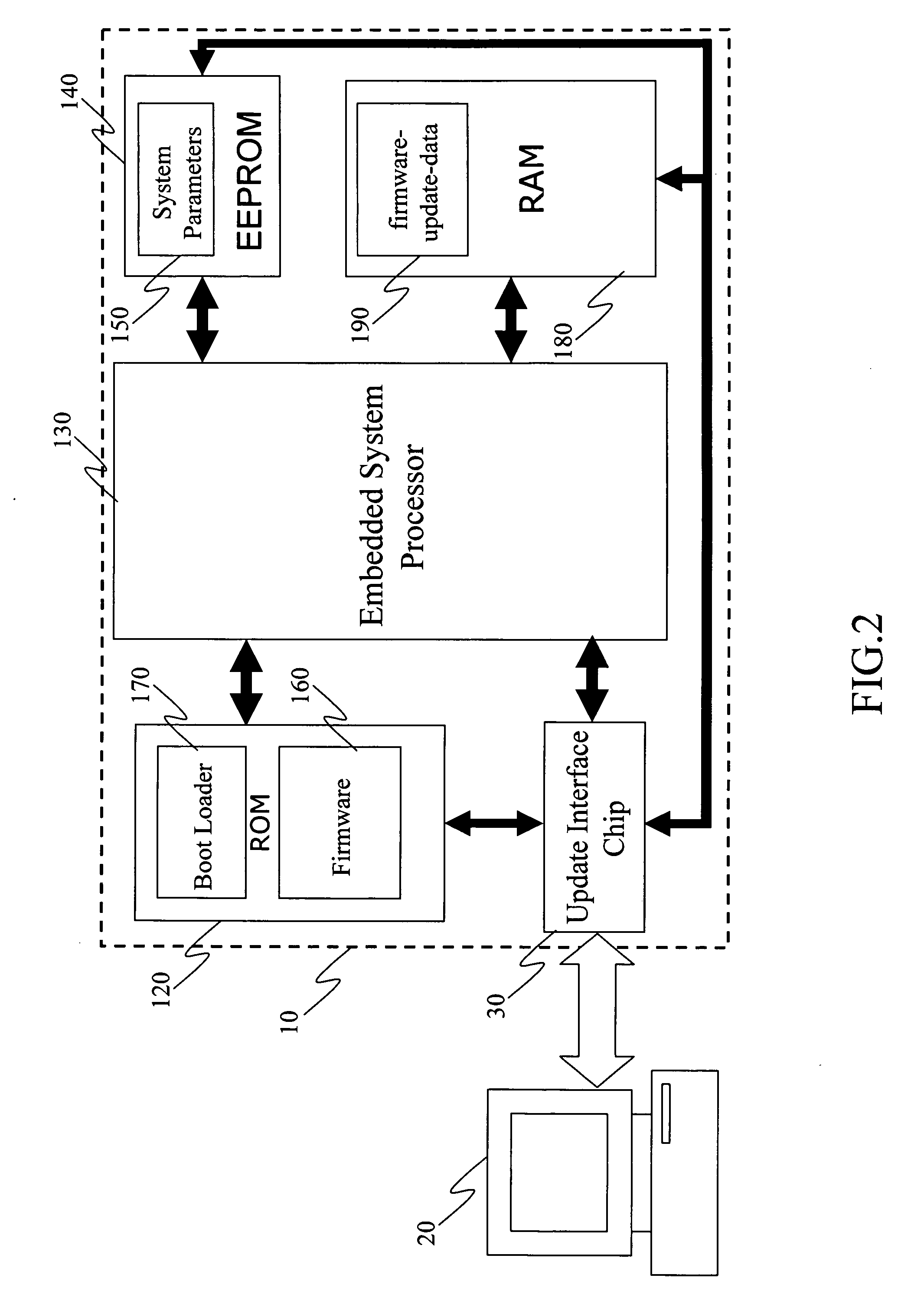
[0014] In order to achieve the above-mentioned objective, the invention provides an update interface chip and two system configurations utilizing such chips in realizing the software update. In the system configuration of the invention, in addition to the update interface chip, three additional buses are provided connecting respectively to the RAM (Random Access Memory), ROM (Read Only Memory) and the EEPROM (Electrically Erasable Programmable Read Only Memory), so that the downloaded firmware-update-data can be written directly into the memory according to its destination address for firmware update without having to go through the processing of the embedded system processor. Or, the firmware, system parameter, the application program and the document files which originally are distributed in the various embedded system memories and may be put together and merged into an update interface memory so that the number of the bus in the system can remain unchanged, and thus the power required for the firmware update can be obtained through the USB (universal serial bus) without having to use the power of the embedded system itself, so as to achieve the objective of firmware update. As such, the system design can be simplified and the production cost can be reduced. In addition, the update interface memory may be simulated and realized as the MSC(Mass Storage Class) disk by making use of the update interface chip. Thus, the firmware-update-data can be written into the memory directly by means of such a mechanism.

Problems solved by technology

For the newly announced product, usually the software / hardware integration may have not been fully tested.
Thus it happens quite often that there may still exist a few problems in the product.
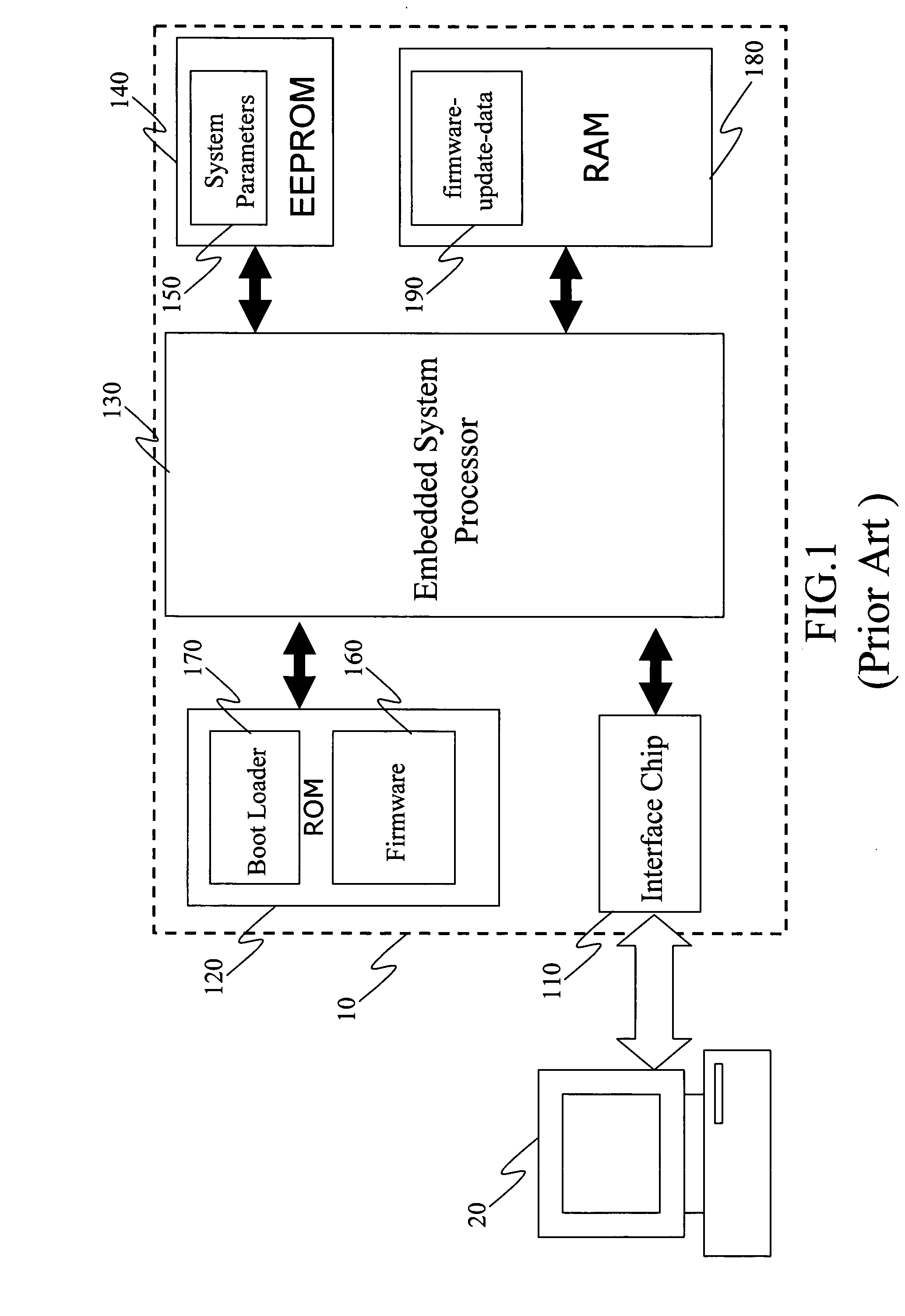
However, in the aforementioned firmware update method and device of the prior art, there still exist quite a few problems.
Firstly, since the firmware 160 is the OS (Operation System) of the embedded system, the firmware having incomplete and inadequate functions is not capable of operating fully the update program.
Thus, even with the upgraded firmware update file provided by the manufacturer, the firmware update may still not be able to be performed.
Secondly, sometimes the power management program in the firmware 160 is out of order, so that the embedded system 10 cannot be powered on and the firmware update cannot be performed.
Thirdly, another reason that the embedded system is not able to be operated is that the Boot Loader 170 stored in the ROM 120 is damaged due to human operation errors, thus results from voltage instability or short circuit.
Under these circumstances, even if repairs may be done by making use of firmware update, since the embedded system cannot be powered on, the firmware 160 cannot be loaded in by the CPU to perform the update required.
Due to the fact that the design of the program developer may not be perfect, or the user may not understand the operation instructions thoroughly before executing the update, version mismatching among the three items may occur.
Therefore, the user lacks the benefit of smooth and efficient system operation by making use of the firmware update, and is subject to inconveniences.
Thus, the benefit of the firmware update functions provided by the manufacturer cannot be realized.
From the above discussion it is evident that the firmware update utilized presently has its problems and shortcomings, and in particular human error in its related operation processes may result in very serious consequences.

Method used


Image

  • Embedded system self-updating method and device
  • Embedded system self-updating method and device
  • Embedded system self-updating method and device

Examples


first embodiment

[0029] Refer to FIG. 2 for a schematic diagram of the system structure of the invention according to the invention, which is an improvement of the embedded system of the prior art. As shown in FIG. 2, the unique feature of the invention is that in the embedded system 10 of the prior art, the update of the firmware 160 must be performed by the embedded system processor 130. However, if any of the system parameters 150, the firmware 160, or the Boot Loader 170 is out of order, then the system-boot can not be performed, and the subsequent firmware update and the related repairs cannot proceed. In view of the shortcomings of the prior art, the invention provides an additional update interface chip 30 in the embedded system 10, which is connected directly and independently to a computer 20 and can be operational without necessitating system activation by the embedded system processor 130. In addition, the update interface chip 30 is connected to the computer 20 through the USB(Universal ...

second embodiment

[0032] However, in the aforementioned system structure, the addition of the extra buses increases the complexity in the design of circuit wiring and thus increases the production cost, so that the original system structure requires proper adjustment. Refer to FIG. 4 for a schematic diagram of the invention according to the invention. As shown in FIG. 4, the original system structure is rearranged with the formation of a system update interface 40 in the embedded system 10. Compared with the embedded system of the prior art, as shown in FIG. 1, in the embedded system 10 of the invention, the number of buses remains at 4. However, the firmware 160, the system parameters 150, the application program 630, and the documents 640 are all gathered together and put into the newly created update interface memory 50, which is composed mainly of the ROM that does not constantly require power to maintain its data, such as the EEPROM, the Serial Interface ROM, or the Parallel Interface ROM. As su...


PUM


Abstract

An embedded system self-updating method and device. When the embedded system connecting to the computer is utilized to perform the firmware update, the update interface chip communicates directly with the computer and obtains from it the firmware-update-data, which is then written into the memory according to its respective destination address, thus achieving the update of the firmware.

Description

BACKGROUND OF INVENTION [0001] 1. Field of the Invention [0002] The invention relates to a method and a device used for updating the embedded system firmware, and in particular to an embedded system in which a newly added update interface chip is used to enable the embedded system to have self-updating capability, so as to update the firmware. [0003] 2. Related Art [0004] With the advent of the intelligent household appliance, the research and development of the embedded system for use in such household electronic appliances has become ever more important. Nowadays, the applications of the various embedded systems in household electrical appliances are enormous, such as the microwave oven, the refrigerator, the washing machine, the TV set and the like. [0005] Originally, these were designed to provide only some basic functions. However, due to the rapid progress of science and technology, these household appliances are now developed to provide full-fledged 3C (computer, communicatio...

Claims


Application Information

Patent Timeline
Patent Type & Authority Applications(United States)
IPC IPC(8): G06F9/44
CPCG06F8/65
Inventor LIN, FAN-SHENG
Owner ETROVISION TECH
Learn More