Semiconductor device and method of manufacturing the same

a technology of magnetic field and semiconductor, applied in semiconductor devices, semiconductor/solid-state device details, electrical apparatus, etc., can solve the problems of reducing the thickness of the bit line mask layer, limiting the gap-fill margin, and difficult to form a minute contact hole, etc., to achieve the effect of reducing the height of the wiring, increasing the gap-fill margin, and reducing the aspect ratio of the wiring

Inactive Publication Date: 2006-11-23
SAMSUNG ELECTRONICS CO LTD
View PDF15 Cites 90 Cited by
  • Summary
  • Abstract
  • Description
  • Claims
  • Application Information

AI Technical Summary

Benefits of technology

[0031] According to the present invention, the contact patterns and contact spacers, which are composed of materials having etching selectivities relative to the silicon oxide based materials, are formed on the wiring. Then, using the contact patterns and the contact spacers as etching masks, the insulating films composed of silicon oxide based materials are etched to form the contact holes between the wiring. Since the contact patterns and contact spacers protect the conductive film patterns of the wiring during an etching process for forming the contacts, a thickness of the second insulating film pattern of the wiring can be minimized to decrease the height of the wiring. Therefore, the aspect ratios of the wiring can be reduced to increase a gap-fill margin between the wiring.
[0032] In addition, since the contact hole between the wiring, e.g., the storage node contact hole, is not formed by a self-aligned contact etching process, a shoulder margin of the wiring can be maintained to prevent an electrical short-circuit between the wiring and the contact plug formed in the contact hole.
[0033] Additionally, a parasitic capacitance between the wiring or between the wiring and the contact plug can be reduced because the spacers, which are composed of the silicon oxide based materials with low dielectric constants, are formed on the sidewalls of the wiring.

Problems solved by technology

As a result, the formation of a minute contact hole may become very difficult through conventional methods of forming contact holes.
If the thickness of the bit line mask layer is reduced to settle this problem, bit line notching may occur due to a low etching selectivity between the photoresist and the silicon nitride.
However, in the above methods, a reduction in the thickness of the bit line mask layer may limit the gap-fill margin of an interlayer dielectric film or decrease the shoulder margin of a bit line during an etching process for a self-aligned contact.

Method used


Image

  • Semiconductor device and method of manufacturing the same
  • Semiconductor device and method of manufacturing the same
  • Semiconductor device and method of manufacturing the same

Examples


embodiment 1

[0043]FIGS. 2A to 2F are cross-sectional views illustrating a method of manufacturing a semiconductor device according to a first embodiment of the present invention.

[0044] Referring to FIG. 2A, a first insulating film 52, a conductive film 53, and a second insulating film 55 are successively formed on a semiconductor substrate 50. That is, a silicon oxide based material is deposited on the semiconductor substrate 50 to form the first insulating film 52, and then the conductive film 53 is formed on the first insulating film 52. Preferably, the conductive film 53 includes a composite film that has a first film composed of a first metal and / or a compound of the first metal, e.g., titanium (Ti) / titanium nitride (TiN), and a second film composed of a second metal, e.g., tungsten (W). Next, silicon nitride is deposited on the conductive film 53 to form the second insulating film 55.

[0045] Alternatively, before forming the conductive film 53, the first insulating film 42 can be partiall...

embodiment 2

[0064]FIGS. 3A and 3B are cross-sectional views illustrating a method of manufacturing a semiconductor device according to a second embodiment of the present invention. The method of the present embodiment is substantially similar to embodiment 1 except it specifies planarizing the third insulating film 61 until the surfaces of the wiring 58 is exposed.

[0065] Referring to FIG. 3A, with processes substantially identical to those described in FIGS. 2A and 2B, after a first insulating film 52 is formed on a semiconductor substrate 50, the wiring 58 including conductive film patterns 54 and second insulating film patterns 56 are formed on the first insulating film 52.

[0066] Then, a silicon oxide based material is deposited on a surface of the resultant structure including the wiring 58 to form a third insulating film 61. Using a planarization process, such as a CMP process or an etch-back process, the third insulating film 61 is partially removed until the surfaces of the second insul...

embodiment 3

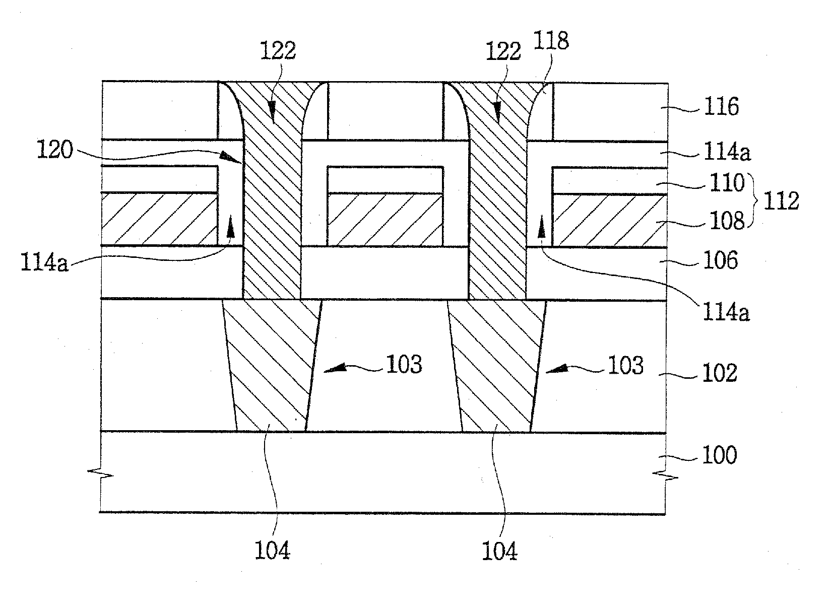
[0073]FIG. 4 is a cross-sectional view of a DRAM device in accordance with a third embodiment of the present invention.

[0074] Referring to FIG. 4, metal oxide semiconductor (MOS) transistors (not shown) having gate electrodes for word lines, capacitor contact regions (source regions), and bit line contact regions (drain regions), are formed on a semiconductor substrate 100. Each gate electrode includes a gate insulating film, a gate capping film composed of silicon nitride and a gate sidewall spacer composed of silicon nitride.

[0075] An interlayer dielectric film 102, composed of silicon oxide, is formed on the substrate 100 to cover the MOS transistors. Contact holes 103 penetrate the interlayer dielectric film 102 to expose the source / drain regions. The contact holes 103 are self-aligned relative to the gate electrodes, respectively. Pad electrodes 104, composed of doped polysilicon, are formed in the self-aligned contact holes 103, respectively. The pad electrodes 104 are node-...


PUM


Abstract

Disclosed herein are a semiconductor device and a method of manufacturing the same that increases the reliability of these devices as size design limitations decrease. Generally, a first insulating film, and wiring, including conductive film patterns and second insulating film patterns are formed on a substrate. Third insulating film patterns including a silicon-oxide-based material are formed on sidewalls of the wiring, and contact patterns and spacers on the sidewalls thereof for defining contact hole regions are formed on the wiring. The contact holes contact surfaces of the third insulating film patterns and pass through the first insulating film. Thus, the thickness of a second insulating film pattern used in the wiring can be minimized, thereby increasing a gap-fill margin between the wiring. A parasitic capacitance between the wiring can be reduced because silicon oxide spacers with a low dielectric constant are formed on sidewalls of the wiring.

Description

CROSS REFERENCE TO RELATED APPLICATIONS [0001] This application is a Divisional of U.S. patent application Ser. No. 10 / 719,624, filed on Nov. 20, 2003, now pending, which claims priority under 35 U.S.C. § 119 to Korean Patent Application No. 2003-03359, filed on Jan. 17, 2003, the contents of which are herein incorporated by reference in their entirety for all purposes.BACKGROUND OF THE INVENTION [0002] 1. Field of the Invention [0003] The present invention relates generally to a semiconductor device, and more particularly, to a dynamic random access memory (DRAM) device and a method of manufacturing the same. [0004] 2. Description of the Related Art [0005] As the technology for manufacturing semiconductor devices has progressed and become more developed, because of increasing demands for products that utilize memory devices, there has been a demand to provide larger capacity memory devices. To help meet this demand, the integration density of a DRAM device whose memory cell is comp...

Claims


Application Information

Patent Timeline
Patent Type & Authority Applications(United States)
IPC IPC(8): H01L29/94H01L21/283H01L21/28H01L21/311H01L21/60H01L21/768H01L21/82H01L21/8242H01L23/522H01L27/10H01L27/108
CPCH01L21/31144H01L21/76834H01L21/7684H01L21/76897H01L27/10855H01L2924/0002H01L27/10885H01L2924/00H01L21/76831H10B12/0335H10B12/482H01L21/28
Inventor LEE, JU-YONGLEE, KYU-HYUN
Owner SAMSUNG ELECTRONICS CO LTD
Why Eureka
Try Eureka