Smoke detector and method of detecting smoke

a detector and smoke detector technology, applied in the direction of fire alarms, fire alarm smoke/gas actuation, instruments, etc., can solve the problems of high false alarm rate, high complexity of ionization-type smoke detectors, and large sensitivity of detectors to dust and dirt accumulation, etc., to achieve low cost, small size, and low complexity

Active Publication Date: 2006-11-23
GE SECURITY INC
View PDF41 Cites 81 Cited by
  • Summary
  • Abstract
  • Description
  • Claims
  • Application Information

AI Technical Summary

Benefits of technology

[0017] Among the advantages of smoke detectors and methods according to certain embodiments of the present invention is that they can be configured to be sensitive to all smoke colors, they can be configured to be relatively small in size and of relatively low complexity and they can be configured to require no cleaning during their lifetime (e.g., approximately 20 years). They can also be configured to be relatively low in cost and to be relatively easy to manufacture. In addition, they can be configured to automatically calibrate themselves, to detect relatively small particles and / or to measure particle size. Further, they can be configured to be used in air duct and / or other locations with a high rate of air flow.

Problems solved by technology

In view of the above, when an ionization-type smoke detector is configured to be sensitive even to smoke particles that only slightly disrupt the ionic current therein, the detector will be overly sensitive to the presence of smoke particles that substantially disrupt the ionic current.
Thus, ionization-type smoke detectors tend to have a high incidence of false alarms.
However, because the color of the smoke particles greatly affects the amount of light that the particles scatter, photoelectric-type smoke detectors respond to the presence of black smoke much more slowly than they respond to the presence of white smoke.
For example, both of these types of detectors are highly sensitive to dust and dirt accumulation in their detection chambers.
In photoelectric-type smoke detectors, dust particles that accumulate on the detection chamber walls scatter light onto the light sensor and thereby cause false alarms and increase background noise.
Hence, stray light propagating from the light source reflects off of the dust layer and increases the amount of light that reaches the light sensor.
Unfortunately, cleaning a detector is expensive, inconvenient and / or time-consuming.
However, the overall cost and complexity of such smoke detectors is relatively high.
In view of these shortcomings, ionization-type detectors cannot be used in air ducts or near wind drafts because the excessive air flow can blow the ions out of the detection chamber.
However, these partitions and walls often significantly decrease the flow of air carrying smoke particles into the detection chamber, thereby reducing the responsiveness of the detector.
However, the incidence of false alarms increased.
However, the combination smoke detector displayed decreased sensitivity to many of the different types of smoke.

Method used


Image

  • Smoke detector and method of detecting smoke
  • Smoke detector and method of detecting smoke
  • Smoke detector and method of detecting smoke

Examples


first embodiment

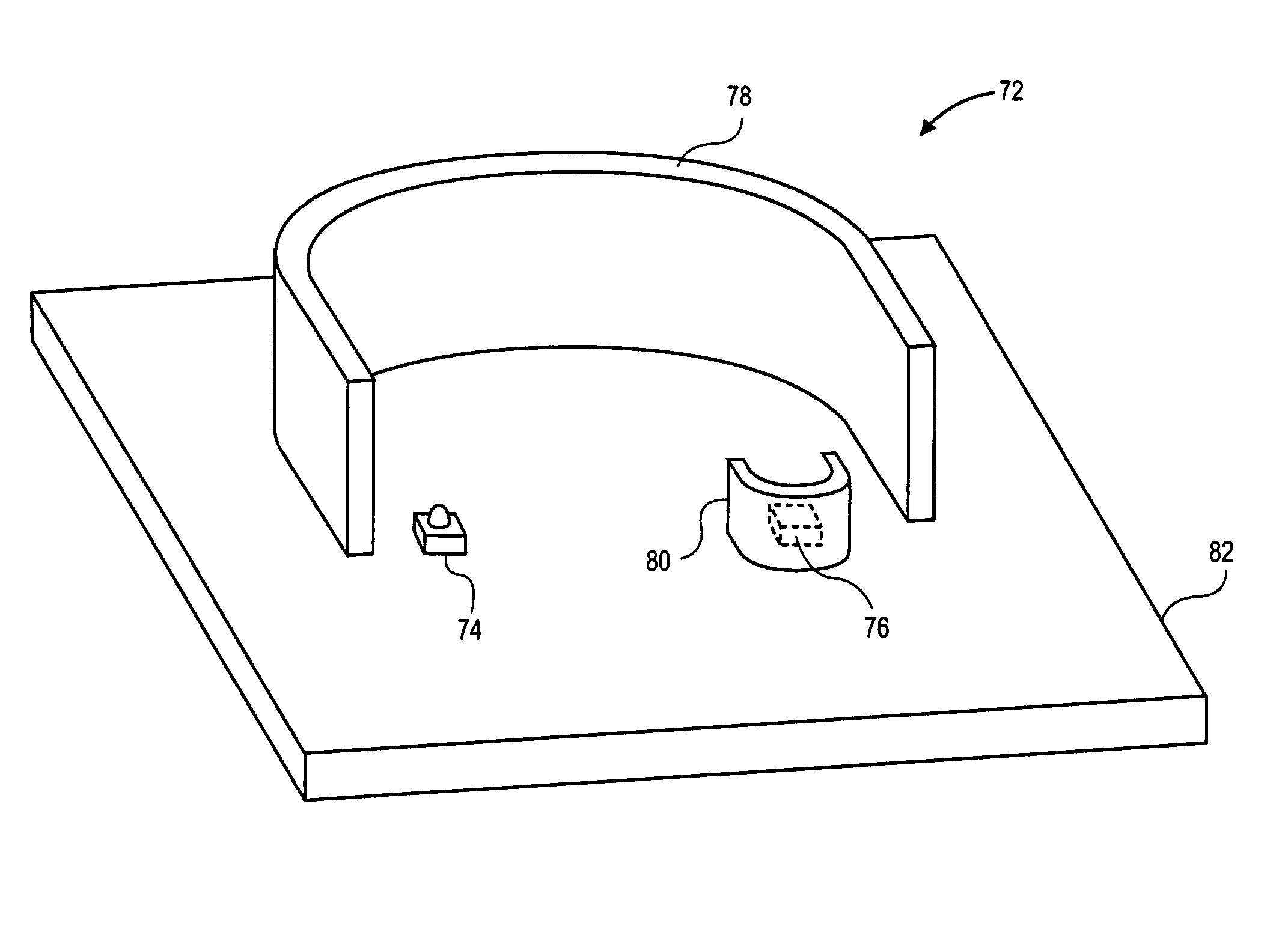
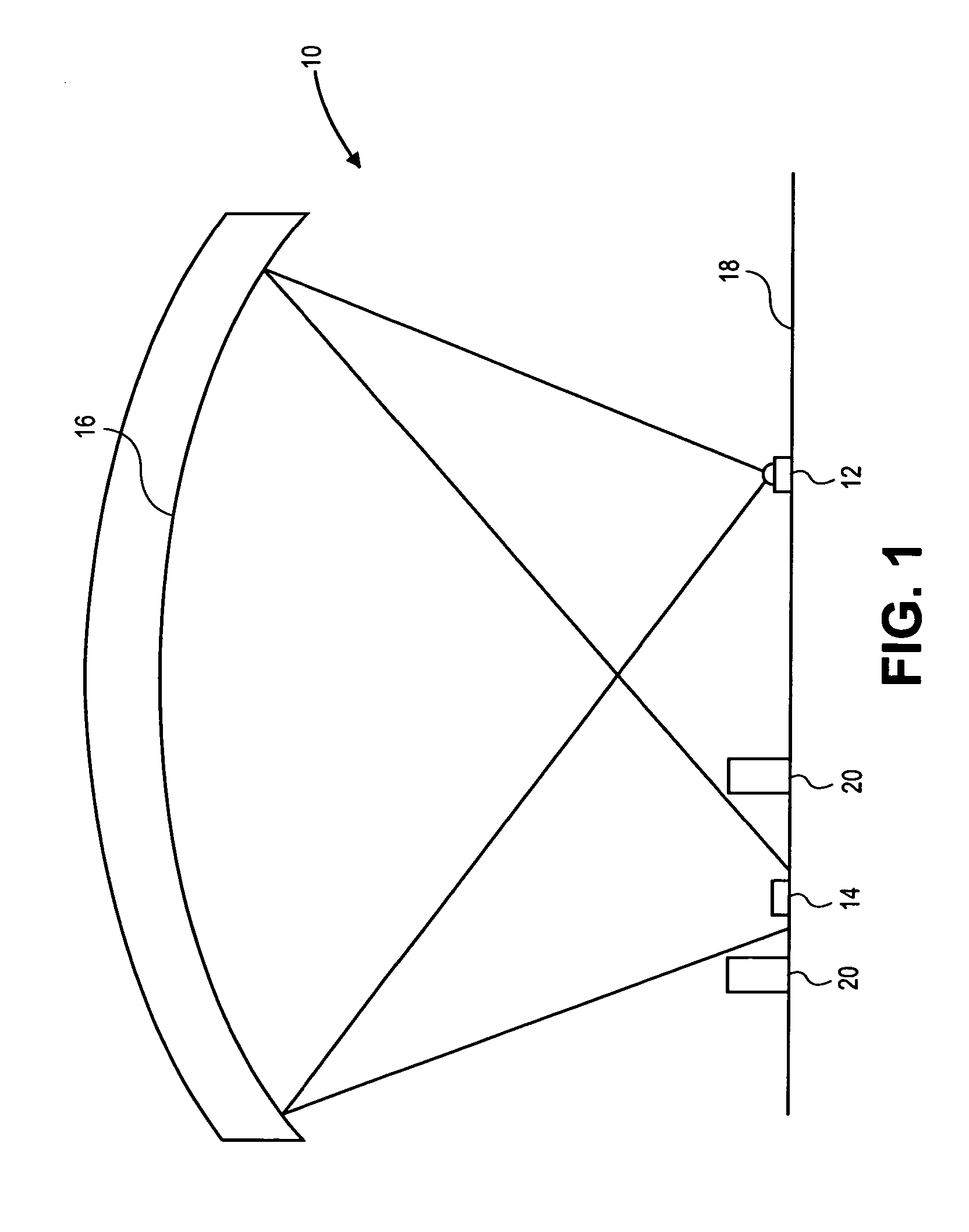
[0033]FIG. 1 illustrates a cross-sectional view of a portion of a smoke sensing chamber 10 of a smoke detector according to the present invention. The smoke sensing chamber 10 typically has all of the openings leading thereto covered at least by a screen (not illustrated) that prevents bugs from entering the chamber 10. However, the smoke sensing chamber 10 typically does not have any predefined sidewalls other than where the housing of the smoke detector that includes the sensing chamber 10 happen to be positioned.

[0034] The smoke sensing chamber 10 includes a light source 12 that, in FIG. 1, takes the form of a Light Emitting Diode (LED). The light source 12 illustrated in FIG. 1 is configured to emit, from a first area thereon, light in a specified wavelength range. According to certain embodiments of the present invention, the specified wavelength range includes the full visible spectrum and / or overlaps at least somewhat with the infrared (IR) and / or ultraviolet (UV) ranges. Acc...

second embodiment

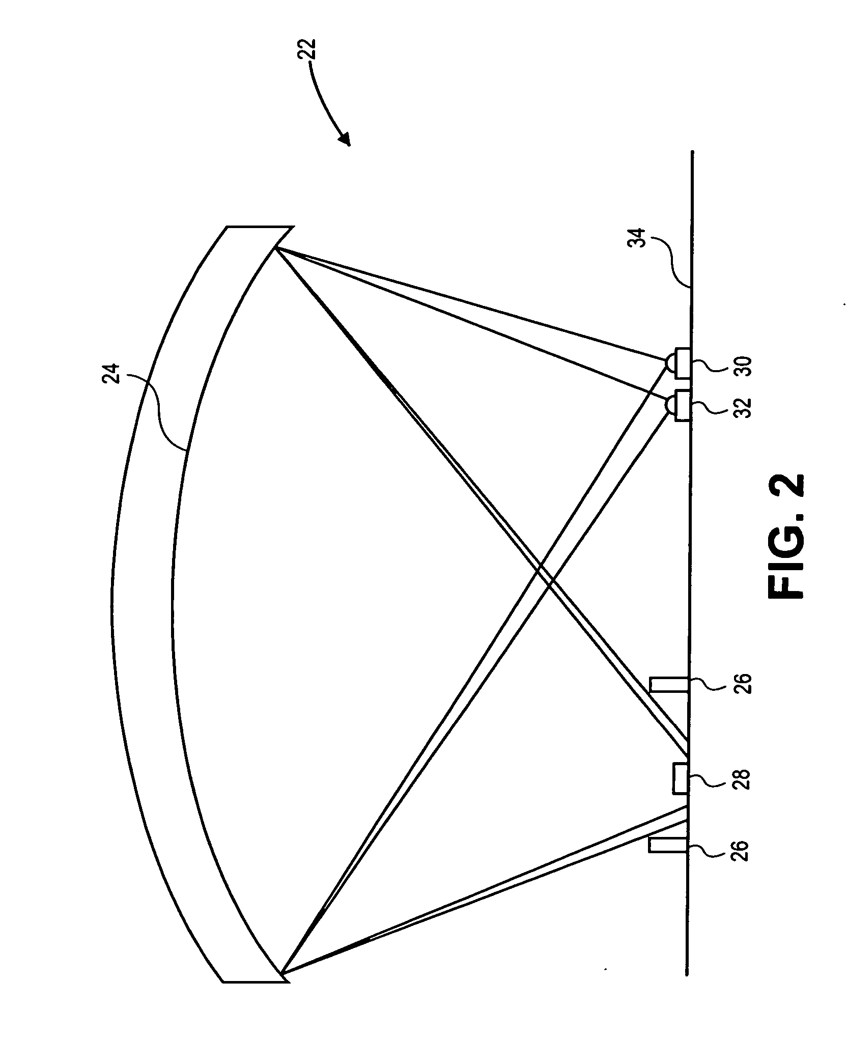
[0040]FIG. 2 illustrates a cross-sectional view of a portion of a smoke sensing chamber 22 of a smoke detector according to the present invention. The smoke sensing chamber 22 includes a reflective surface 24, a shroud 26 and a light sensor 28 that are similar to the reflective surface 16, shroud 20 and light sensor 14 illustrated in FIG. 1, respectively.

[0041] The smoke sensing chamber 22 illustrated in FIG. 2 also includes a first light source 30 and a second light source, each of which is analogous to the light source 12 illustrated in FIG. 1 at least in the sense that each may emit V, near-UV, visible, near-IR and / or IR light. According to certain embodiments of the present invention, the first light source 30 is configured to emit light in a first wavelength range onto the reflective surface 24 and the second light source 32 is configured to emit light in a second wavelength range onto the reflective surface 24.

[0042] Typically, the second wavelength range differs from the fir...

third embodiment

[0044]FIG. 3 illustrates a cross-sectional view of a portion of a smoke sensing chamber 36 of a smoke detector according to the present invention. In FIG. 3, a first light source 38, a second light source 40, a first light sensor 42 and a second light sensor 44 are all surface-mounted on a circuit board 46. Positioned directly opposite to the circuit board 46 is a reflective surface 48.

[0045] According to certain embodiments of the present invention, the first light source 38 includes an LED that emits light in a first wavelength range (e.g., UV light) and the second light source 40 includes an LED that emits light in a second wavelength range (e.g., IR light). According to some of these embodiments, the first light sensor 42 includes a photodiode that is configured to detect the light in the first wavelength range and the second light sensor 44 includes a photodiode that is configured to detect the light in the second wavelength range.

[0046] Although the first light source 38 and ...


PUM

PropertyMeasurementUnit
diameteraaaaaaaaaa
surface areaaaaaaaaaaa

Abstract

A smoke detector that includes at least one image-forming reflective surface, at least one light source and at least one light sensor. In operation, at least one light source emits light from a first area thereon and the reflective surface focuses the light onto a second area that includes at least one light sensor, wherein the first area is smaller than the second area.

Description

CROSS-REFERENCE TO RELATED APPLICATIONS [0001] This application claims priority to and is a continuation-in-part of U.S. patent application entitled, RAPIDLY RESPONDING, FALSE DETECTION IMMUNE ALARM SIGNAL PRODUCING SMOKE DETECTOR, filed Aug. 20, 2003, having a Ser. No. 10 / 645,354, now pending, the disclosure of which is hereby incorporated herein in its entirety by reference and which itself claims priority to provisional U.S. patent application entitled, RAPIDLY RESPONDING, FALSE DETECTION IMMUNE ALARM SIGNAL PRODUCING SMOKE DETECTOR, filed Aug. 23, 2002, having a Ser. No. 60 / 405,599, the disclosure of which is also hereby incorporated herein in its entirety by reference.FIELD OF THE INVENTION [0002] The present invention relates generally to smoke detectors and to fire detection methods. More particularly, the present invention relates to obscuration-type smoke detectors and to methods of using the same. BACKGROUND OF THE INVENTION [0003] Ionization-type smoke detectors and photo...

Claims


Application Information

Patent Timeline
Patent Type & Authority Applications(United States)
IPC IPC(8): G08B17/10G08B17/103G08B29/26
CPCG08B17/103G08B17/113G08B29/26
Inventor MARMAN, DOUGLASEGGERS, FREDERICK
Owner GE SECURITY INC
Why Eureka
Try Eureka