Internally illuminated sign

Inactive Publication Date: 2006-11-30
KORRAL MENACHEM +2
View PDF9 Cites 65 Cited by
  • Summary
  • Abstract
  • Description
  • Claims
  • Application Information

AI Technical Summary

Benefits of technology

[0008] The present invention seeks to provide a new method and apparatus for providing uniform illumination on the display screen of an internally illuminated sign, such as is generally illuminated from an end by means of an optical source. The method is based on the application of a curvature to the display screen, which compensates for the effect of the fall-off of illumination with distance from the source. For any uniform source, having an approximately uniform angular intensity profile over its useable angular range, each angular segment provides the same luminous flux. However, angular segments illuminating regions of the screen further from the source provide a lower level of illumination on the screen, because of the increased area which the divergence of the angular segment must illuminate. In order to compensate for this decreased illumination, the display screen, according to the present invention, is curved inwards towards the illum

Problems solved by technology

However, angular segments illuminating regions of the screen further from the source provide a lower level of illu

Method used


Image

  • Internally illuminated sign
  • Internally illuminated sign
  • Internally illuminated sign

Examples


Example

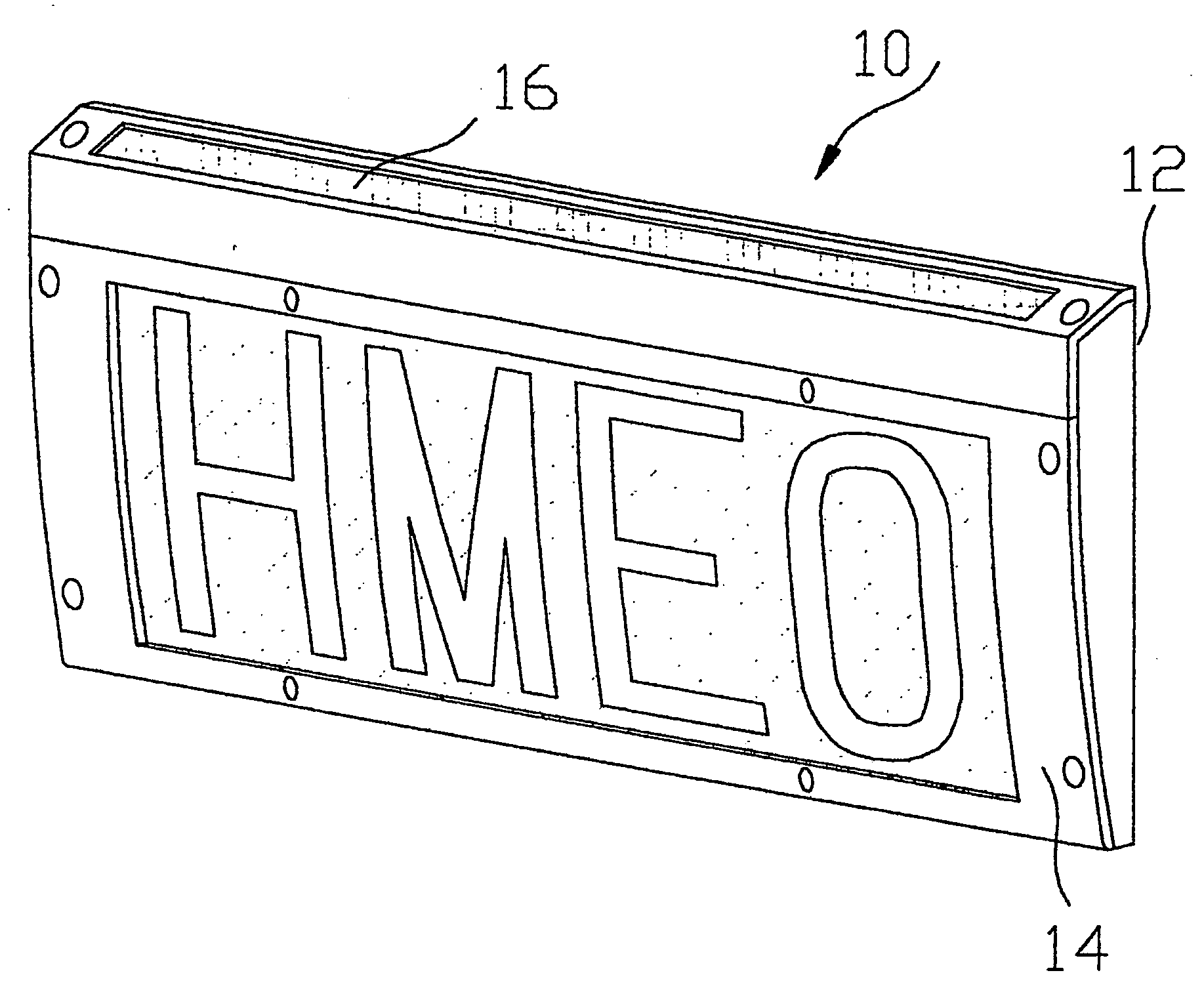
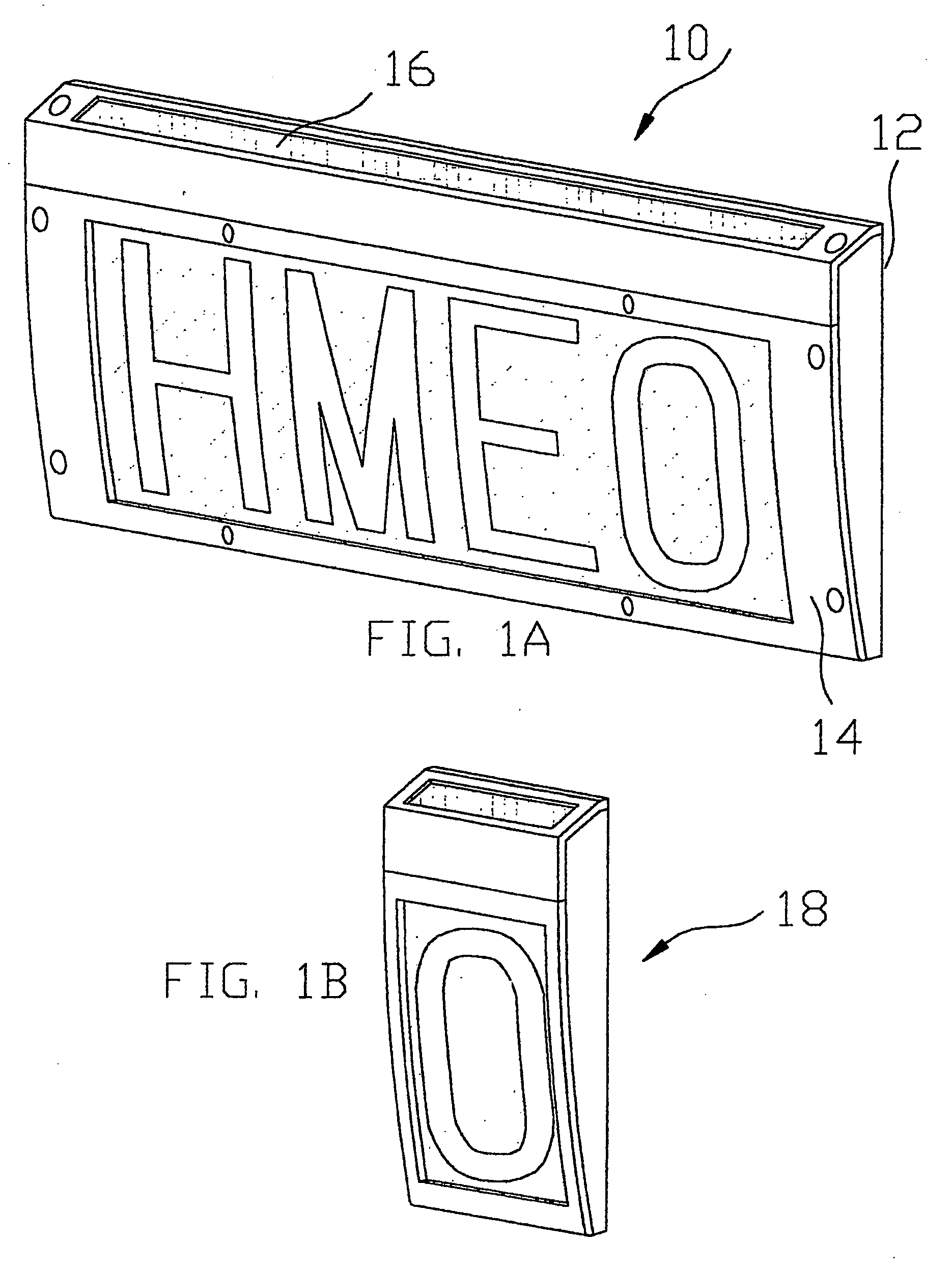
[0057] Reference is now made to FIG. 1A, which is an isometric schematic view of a solar-powered, internally illuminated, single-sided, multiple character sign 10, constructed and operative according to a first preferred embodiment of the present invention. The body of the sign preferably has a flat rear surface 12 for mounting of the sign on a wall, and a convex curved front surface 14, displaying the sign character or characters. When the sign is to be solar powered with an internal rechargeable battery, a solar panel 16 may be disposed, preferably at the top part of the sign 10, such that it faces the general direction of ambient incident light. FIG. 1B shows a single digit sign 18, constructed in a similar way to the multi-digit sign of FIG. 1A, to illustrate how a sign of any size may be built up of individual digit signs.

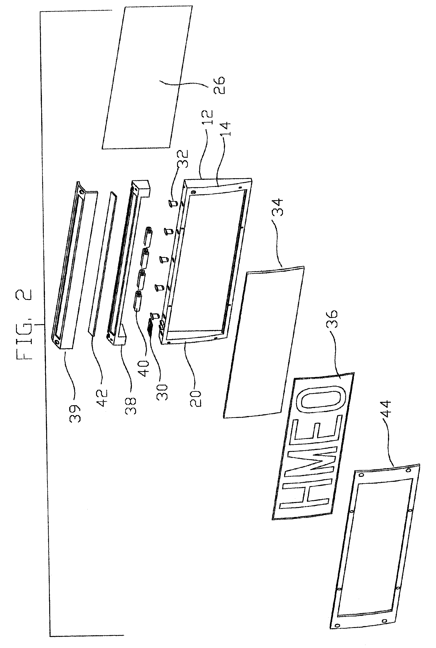
[0058] Reference is now made to FIG. 2, which is an exploded, isometric view of an internally illuminated sign, similar to that shown in FIG. 1, showing the ...


PUM


Abstract

An illuminated sign, internally illuminated by a source such as one or more LED'S generally located at one end, and having a character panel with at least partially transmissive portions to define the characters of the sign. The character panel is curved so as to face the source more squarely at distances further from the source. By this arrangement, the geometric fall-off of illumination with increasing distance from the source is compensated for by the curvature of the character panel, such that more uniform illumination is provided than with prior art flat panels. Power management systems for solar charged illuminated signs are also described, in which the illumination level of the sign is adjusted according to the ambient solar flux and according to the charge-holding capacity of the battery. The system also warns of the impending end of battery life without interrupting the sign functionality.

Description

REFERENCE TO PRIOR APPLICATIONS [0001] This application is a continuation in parts, and claims the benefit of priority to, PCT application No. PCT / IL2004 / 000850, filed Sep. 14, 2004, which in turn claims the benefit of priority to U.S. provisional application No. 60 / 504,945, filed Sep. 15, 2003. Both the above identified applications are incorporated herein by reference in their entirety.FIELD OF THE INVENTION [0002] The present invention relates to the field of internally illuminated signs, and especially those having uniform illumination over their operative area and having a very low energy requirement for their operation. BACKGROUND OF THE INVENTION [0003] Numerous applications exist which require the use of an illuminated sign for night-time visibility in situations where access to an electric mains supply is either unavailable or inconvenient to supply. Some such applications are in house signs, road signs, directional signs, road milestones, camping sites, emergency signs suc...

Claims


Application Information

Patent Timeline
IPC IPC(8): G09F13/06F21VG08B5/00G09F13/04
CPCG09F13/06G09F13/04Y10S362/812G09F27/007
Inventor KORALL, MENACHEMPERACH, ZVIKORALL, ELIYAHU
Owner KORRAL MENACHEM
Why Eureka
Try Eureka