Reversing flow catalytic converter for internal combustion engines

a catalytic converter and reverse flow technology, applied in the direction of engine components, exhaust treatment, mechanical equipment, etc., can solve the problems of affecting the performance of the engine,

Inactive Publication Date: 2006-11-30
SMART MUFFLER CORP
View PDF13 Cites 6 Cited by
  • Summary
  • Abstract
  • Description
  • Claims
  • Application Information

AI Technical Summary

Benefits of technology

[0010] It is accordingly an object of the present invention to provide an improved reversing flow catalytic converter system for treating exhaust gases from an internal combustion engine, which system includes a compact valve structure incorporated in the converter as well as a safeguard system to protect the catalyst and converter from overheating.

Problems solved by technology

A problem relating to catalytic converters for internal combustion engines, such as the prior art reversing flow catalytic converter for internal combustion engines disclosed in U.S. Pat. No. 6,148,613, is overheating.
Lean burn combustion systems for fuel-efficient vehicles are particularly hard on exhaust after-treatment systems because excessive oxygen is always present in the exhaust.
Under such circumstances, any engine management problems that result in excessive fuel in the exhaust, will generally damage exhaust after-treatment system due to overheating.
If a fuel management problem occurs, a large amount of the excess fuel delivered to the engine can pass through it and into the engine exhaust.
Further temperature rise will cause collapse of the substrate and eventual melt-down will occur when it is heated to 1400-1450° C. A detrimental uncontrolled temperature rise can damage a catalyst in less than 20 seconds.
The large amount of excessive fuel from the engine pulls down the catalyst temperature.
In this type of catalyst protection mode, however, the carbon monoxide content of the exhaust gas is undesirably very high.
However, for lean burn systems such as diesel or dual fuel engines, the excessive fuel will not cool down the catalyst temperature because of the presence of a high concentration of oxygen in the exhaust.
Furthermore, lean burn systems cannot burn stoichiometric fuel / air mixtures because of knocking restrictions.
Engine fuel will need to be added to the exhaust stream during idle and low power operation of the engine in order to maintain an oxidation temperature sufficient to convert Co and hydrocarbons (including particulates), however, a considerably lesser amount of fuel than would be required by a conventional uni-directional oxidation catalyst.
For this reason, addition of fuel can also result in overheating of the catalyst, if too much fuel is added.
Disadvantageously, prior art devices such as the type disclosed in U.S. Pat. No. 6,148,613 lack a safeguard system to protect such reversing flow catalytic converter from overheating, as may arise under any one or more of the conditions explained above.

Method used


Image

  • Reversing flow catalytic converter for internal combustion engines
  • Reversing flow catalytic converter for internal combustion engines
  • Reversing flow catalytic converter for internal combustion engines

Examples


Embodiment Construction

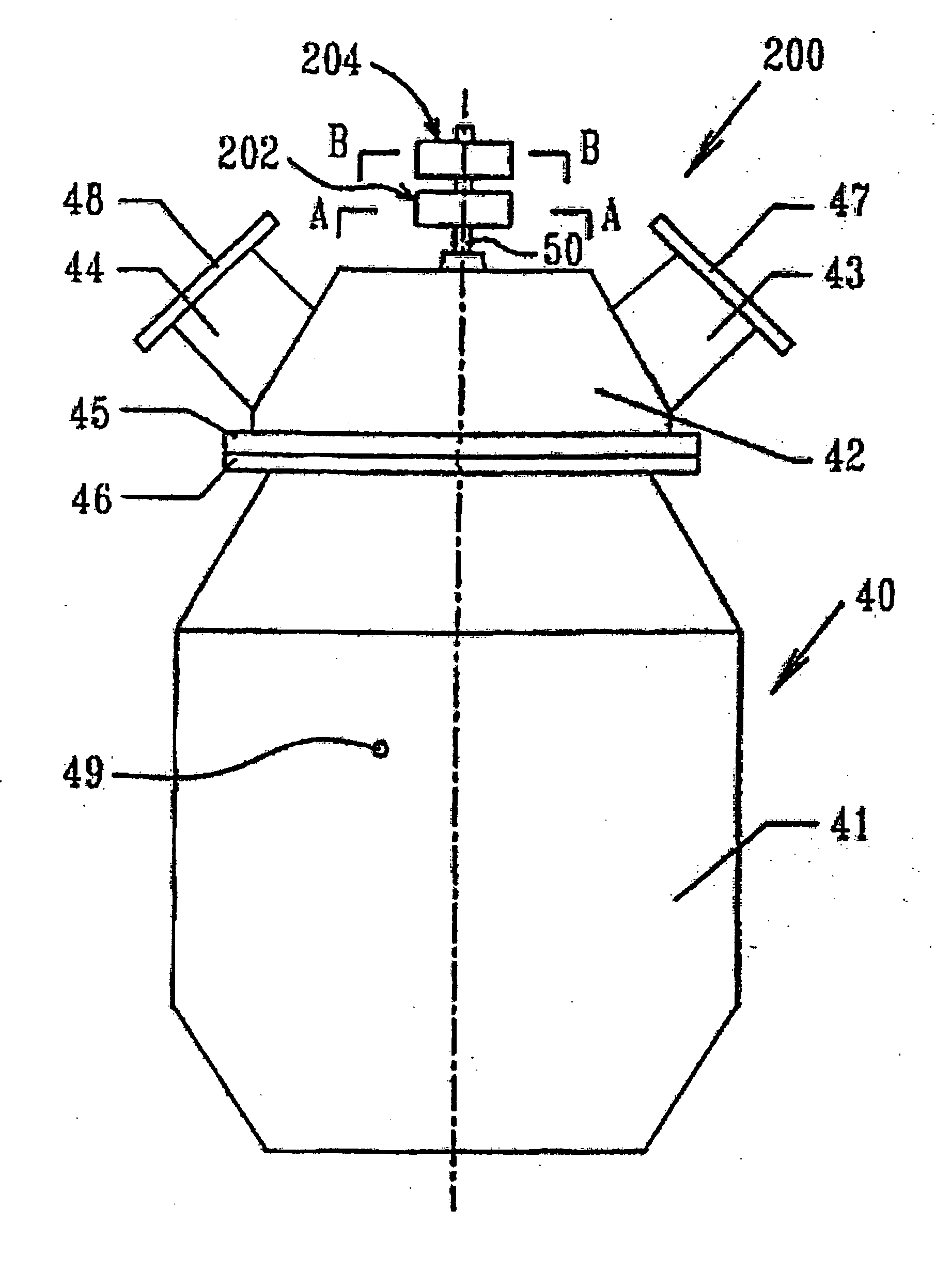
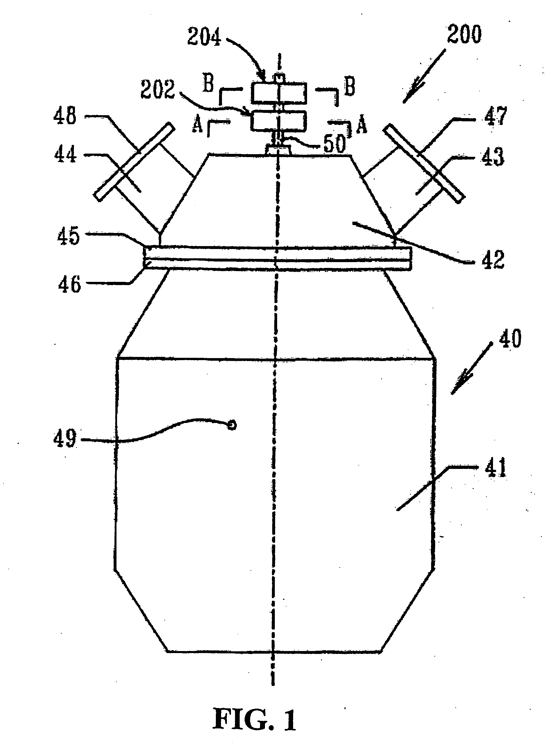
[0062]FIG. 1 illustrates an improved catalytic converter 200 in accordance with an embodiment of the present invention which incorporates a safeguard system to inhibit overheating the catalyst monoliths.

[0063] With reference to FIG. 1, the catalytic converter 200 comprises a container 40 and valve housing 42 with a similar structure and components as described in U.S. Pat. No. 6,148,613. A rotary actuator 202 and a center return mechanism 204 are mounted on the drive shaft 50 of the valve disk 18. The rotary actuator 202 is controlled to periodically rotate the valve disk 18 between the first and the second positions to reverse gas flow through the container 40.

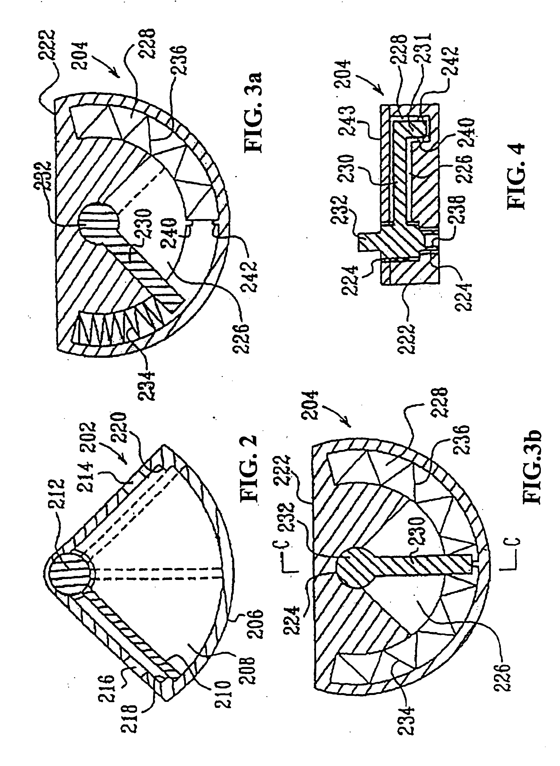
[0064] As shown in FIG. 2, the rotary actuator 202 includes a housing 206 which encloses a pressure chamber 208. A moveable vane 210 is mounted to drive shaft 212 which is adapted to be connected to the shaft 50 of the valve disk 18 to rotate together therewith. The housing 206 has a first opening 214 and a second opening 2...


PUM


Abstract

A compact reversing flow catalytic converter with protection from overheating includes a valve unit which directs exhaust gases through a container filled with catalytic material to permit a bypass of catalytic material when a temperature of the material exceeds a predetermined threshold. The container defines a U-shaped gas passage that communicates with two ports at the top of the container. The valve unit is mounted to the top of the container and includes an intake and an exhaust cavity. The valve unit includes a valve disk having two openings therethrough. The valve disk rotates around perpendicular central axis between a first, a second and third positions. When overheating of the catalytic material is predicted, a controller relinquishes control of the valve disk and a center return mechanism rotates the valve disk to a third position, in which each of the openings communicates with both ports so that the exhaust gas flow bypasses catalytic material. The catalytic material is thus protected from damage due to overheating. The advantage is a compact, reliable, highly efficient catalytic converter that is inexpensive to manufacture, durable, and adapted for extended service life. An alternate version of the compact reversing flow controller is also described wherein the valve unit and container are essentially as described above but the valve disk is a four position disk with the fourth position blocking communication between the valve housing and the container isolating the monolith so that maximum heat is retained during engine shut down. The valve is driven by a stepper motor that moves and holds the valve to its four positions including block, bypass, forward and reverse flow. The alternate version also replaces the oxidizing flow-through monolith with an oxidizing filter trap and adds a fuel injection system under control of the controller so that measured amounts of fuel can be injected into the valve inlet to enhance oxidation.

Description

INTRODUCTION [0001] The present invention relates to catalytic converters for internal combustion engines, and in particular, to an improved reversing flow catalytic converter for treating exhaust gases from internal combustion engines. BACKGROUND OF THE INVENTION [0002] A problem relating to catalytic converters for internal combustion engines, such as the prior art reversing flow catalytic converter for internal combustion engines disclosed in U.S. Pat. No. 6,148,613, is overheating. Lean burn combustion systems for fuel-efficient vehicles are particularly hard on exhaust after-treatment systems because excessive oxygen is always present in the exhaust. For example, the exhaust of diesel dual fuel (DDF) engines, which is one type of diesel engine, normally contains more than 5% volumetric oxygen after combustion. Under partial load the surplus of oxygen in the exhaust may be higher than 10% by volume. Under such circumstances, any engine management problems that result in excessiv...

Claims


Application Information

Patent Timeline
Patent Type & Authority Applications(United States)
IPC IPC(8): F01N3/00F01N3/10
CPCF01N1/084F01N13/0097F01N3/035F01N3/2053F01N3/2093F01N3/24F01N11/002F01N2390/00F01N2410/00F01N2410/02F01N2410/08F01N2470/22F01N2560/06Y02T10/47F01N3/031Y02T10/40
Inventor ZHENG, MINGMIROSH, EDWARD A.READER, GRAHAM T.
Owner SMART MUFFLER CORP
Why Eureka
Try Eureka