Ammonia/CO2 refrigeration system, CO2 brine production system for use therein, and ammonia cooling unit incorporating that production system

Active Publication Date: 2006-11-30
MAYEKAWA MFG CO LTD
View PDF20 Cites 17 Cited by
  • Summary
  • Abstract
  • Description
  • Claims
  • Application Information

AI Technical Summary

Benefits of technology

[0062] According to the invention like this, an effect is obtained in addition to the effect obtained by the first invention that pressure loss between the eliminators can be reduced, since the eliminators positioned adjacent to each other are positioned to be stepped with each other so that the upper part of the side wall of an eliminator faces the lower part of the side wall of the adjacent eliminator, as a result the height of the side wall parts of the eliminators di

Problems solved by technology

However, as ammonia is toxic, a refrigerating cycle, in which an ammonia cycle and CO2 cycle are combined and CO2 is used as a secondary refrigerant in a refrigeration load side, is adopted in many of ice-making factories, refrigerating storehouses, and food refrigerating factories.
However, said prior art includes a fundamental disadvantage that the cascade condenser (which works as an evaporator in the ammonia cycle to cool carbon dioxide) must be located at a position higher than the position of the evaporator (refrigerating showcase, etc.) for performing required cooling in the CO2 cycle.
Particularly, there may be a case that refrigerating showcases or freezer units are required to be installed at higher floors of high or middle-rise buildings at customers' convenience, and the system of the prior art absolutely can not cope with the case like this.
Particularly, the prior art of FIG. 9(B) utilizes the liquid pump on condition that the hydraulic head is secured, that is, on condition that the cascade condenser(an evaporator for cooling carbon dioxide refrigerant) is located at a position higher than the position of the evaporator for performing cooling in the carbon dioxide cycle, and above-mentioned fundamental disadvantage is not solved also in this prior art.

Method used


Image

  • Ammonia/CO2 refrigeration system, CO2 brine production system for use therein, and ammonia cooling unit incorporating that production system
  • Ammonia/CO2 refrigeration system, CO2 brine production system for use therein, and ammonia cooling unit incorporating that production system
  • Ammonia/CO2 refrigeration system, CO2 brine production system for use therein, and ammonia cooling unit incorporating that production system

Examples


Example

Embodiment Example 1

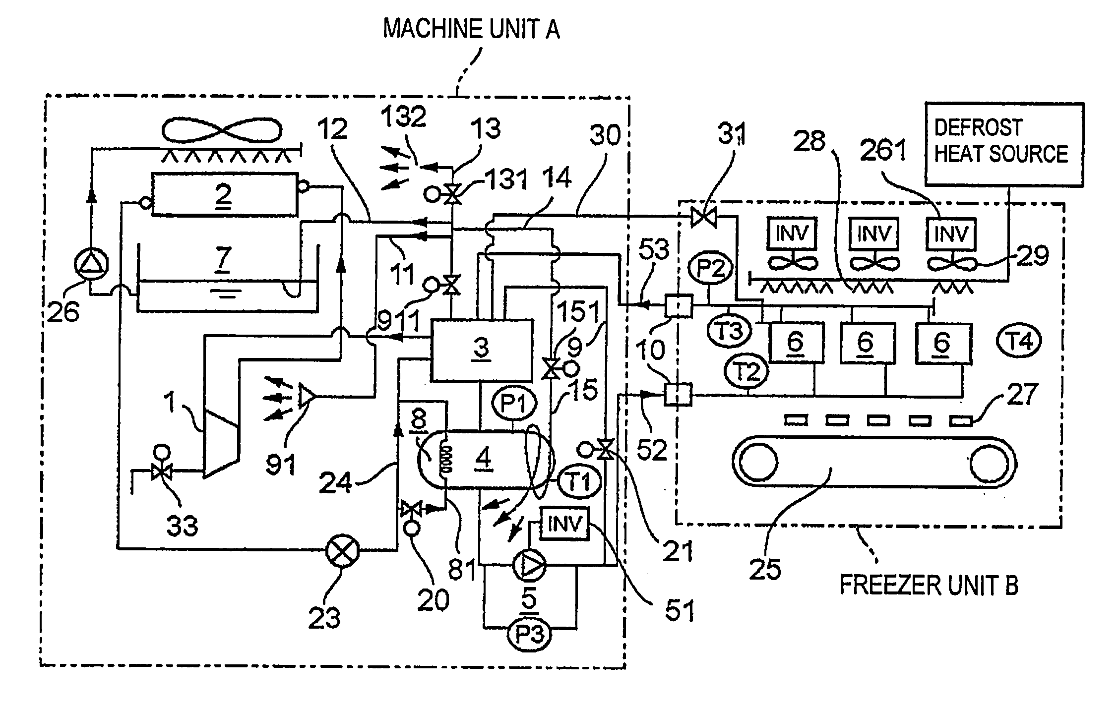
[0091]FIG. 3 is a schematic representation of the refrigerating apparatus of forced CO2 circulation type in which CO2 brine which has cooled a refrigeration load with its latent heat of vaporization is returned to be cooled through the heat exchange with ammonia refrigerant.

[0092] In FIG. 3, reference symbol A is a machine unit(CO2 brine producing apparatus) integrating an ammonia refrigerating cycle part and an ammonia / CO2 heat exchanging part, and B is a freezer unit for cooling(refrigerating) a refrigeration load by utilizing the latent heat of vaporization of CO2 cooled in the machine unit side.

[0093] Next, the machine unit A will be explained.

[0094] In FIG. 3, reference numeral 1 is a compressor, the ammonia gas compressed by the compressor 1 is condensed in an evaporation type condenser 2, and the condensed liquid ammonia is expanded at an expansion valve 23 to be introduced into a CO2 brine cooler 3 through a line 24. The ammonia evaporates in the brin...

Example

Embodiment Example 2

[0127]FIG. 6˜8 show an example when the machine unit of FIG. 3 is constructed such that an ammonia cycle part and a part of carbon dioxide cycle part are unitized and accommodated in an unit to compose an ammonia refrigerating unit.

[0128] As shown in FIG. 6, the ammonia refrigerating unit A of the invention is located out of doors, and the cold heat(cryogenic heat) of CO2 produced by the unit A is transferred to a refrigeration load such as the freezer unit of FIG. 3. The ammonia refrigerating unit A consists of two construction bodies, a lower construction body 56 and an upper construction body 55.

[0129] The lower construction body 56 contains devices of ammonia cycle excluding an evaporation type condenser and a part of devices of CO2 cycle. To the upper construction body 55 are attached a drain pan 62, an evaporation type condenser 2, outer casing 65, a cooling fan 63, etc. The evaporation type condenser 2 is composed of an inclined multitubular heat exchan...


PUM


Abstract

The object of the invention is to provide an ammonia/CO2 refrigeration system in which the ammonia cycle and CO2 brine cycle can be combined without problems even when refrigeration load such as refrigerating showcase, etc. is located at any place in accordance with circumstances of customer's convenience.
The system comprises apparatuses working on an ammonia refrigerating cycle, a brine cooler for cooling and condensing CO2 by utilizing the latent heat of vaporization of the ammonia, and a liquid pump provided in a supply line for supplying the cooled and liquefied CO2 to a refrigeration load side cooler, wherein said liquid pump is a variable-discharge pump for allowing CO2 to be circulated forcibly, and the forced circulation flow is determined so that CO2 is recovered from the outlet of the cooler of the refrigeration load side in a liquid or liquid/gas mixed state.

Description

[0001] This is a continuation of International Application PCT / JP2004 / 000122 having an international filing date of 9 Jan. 2004, and claims priority under 35 U.S.C. § 119(a) to Japanese Application No. JP 2003-391715, filed on 21 Nov. 2003. The disclosure of the PCT and priority applications, in their entirety, including the drawings, claims, and the specification thereof, are incorporated herein by reference.FIELD OF THE INVENTION [0002] The present invention relates to a refrigeration system working on an ammonia refrigerating cycle and CO2 refrigerating cycle, a system for producing CO2 brine to be used therein, and a refrigerating unit using ammonia as a refrigerant and provided with the system for producing CO2 brine, specifically relates to an ammonia refrigerating cycle, a brine cooler for cooling and liquefying CO2 by utilizing the latent heat of vaporization of ammonia, an apparatus for producing CO2 brine to be used for a refrigeration system having a liquid pump in a supp...

Claims


Application Information

Patent Timeline
IPC IPC(8): F25B39/04F25B9/00F25B25/00
CPCF25B9/002F25B9/008F25B2500/01F25B2309/06F25B2339/047F25B25/005F25B23/006F25B1/00F25B9/00F25B25/00
Inventor NEMOTO, TAKASHITANIYAMA, AKIRAAKABOSHI, SHINJIROUTERASHIMA, IWAO
Owner MAYEKAWA MFG CO LTD
Why Eureka
Try Eureka