System, apparatus and method for driving permanent magnet electrical machine

a permanent magnet electrical machine and apparatus technology, applied in the direction of motor/generator/converter stopper, electronic commutator, dynamo-electric converter control, etc., can solve the problems of increasing the complexity of the driver, reducing the reducing the efficiency of the driver, etc., and achieving high efficiency and low cost. , the effect of preventing short circui

Inactive Publication Date: 2006-11-30
KHOPKAR RAHUL VIJAYKUMAR +3
View PDF8 Cites 25 Cited by
  • Summary
  • Abstract
  • Description
  • Claims
  • Application Information

AI Technical Summary

Benefits of technology

[0007] The present invention provides a novel permanent magnet (PM) motor driver that is low cost, rugged, highly efficient, reliable, short circuit immune, compact and lighter than conventional PM motor drivers. The motor driver topology of the present invention is ideal for residential and commercial applications, such as building air conditioning, appliances, etc. The present invention is fault tolerant due to its current regulated nature, where it

Problems solved by technology

The advantages of the BLDC motor come at the expense of increased complexity of the driver.
These switching operations cause switching loss in the IGBTs 110, reducing the driver efficiency as well as dissipating heat.
Moreover, the cost of this BLDC driver 100 is increased because of the IGBT switches

Method used


Image

  • System, apparatus and method for driving permanent magnet electrical machine
  • System, apparatus and method for driving permanent magnet electrical machine
  • System, apparatus and method for driving permanent magnet electrical machine

Examples


Embodiment Construction

[0038] While the making and using of various embodiments of the present invention are discussed in detail below, it should be appreciated that the present invention provides many applicable inventive concepts that can be embodied in a wide variety of specific contexts. The specific embodiments discussed herein are merely illustrative of specific ways to make and use the invention and do not delimit the scope of the invention. It should be understood that the principles and applications disclosed herein can be applied to a wide range of permanent magnet (PM) motor drivers.

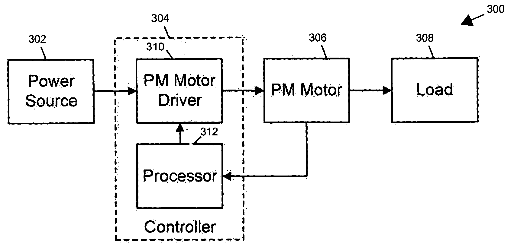
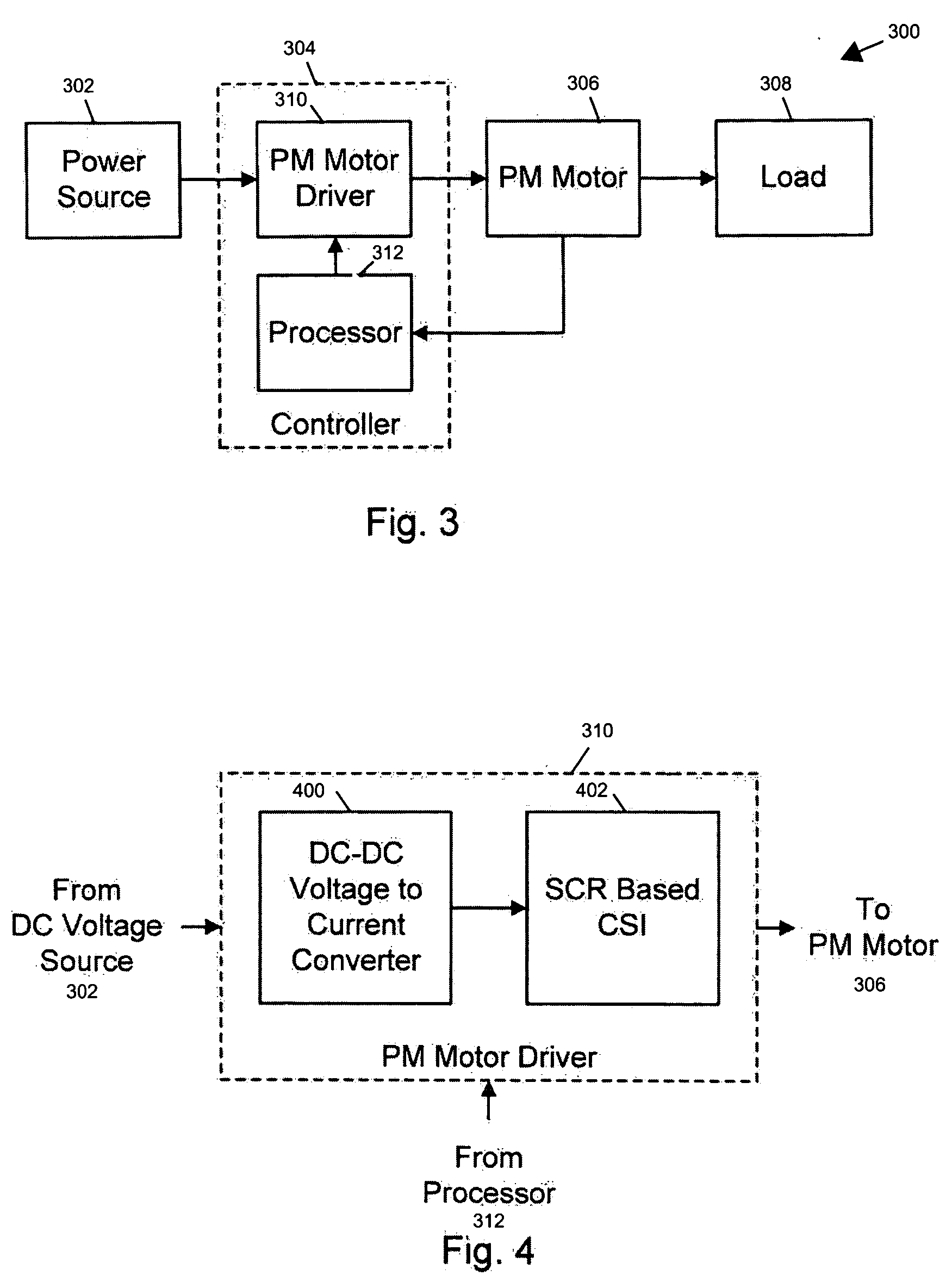
[0039] The present invention provides a novel permanent magnet (PM) motor driver that is low cost, rugged, highly efficient, reliable, short circuit immune, compact and lighter than conventional PM motor drivers. The motor driver topology of the present invention is ideal for residential and commercial applications, such as building air conditioning, appliances, etc. The present invention is fault tolerant due to i...


PUM


Abstract

The present invention provides a system, apparatus and method for driving a permanent magnet (PM) machine supplied by a Current Source Inverter (CSI). A DC-DC voltage to current converter (chopper) with an inductor value inversely related to the operating frequency of the DC chopper for a given DC Link current ripple, acts as a current source for the CSI. The DC source for the DC-DC voltage to current converter can be from a DC power source or supply, or an AC power source or supply electrically connected to a rectifier/Pulse Width Modulated (PWM) rectifier.

Description

[0001] This application claims the benefit of U.S. provision application Ser. No. 60 / 575,928. filed May 31. 2004. entitled “System Apparatus and Method for Driving Permanent Magnet Electric Machine,” the disclosure of which is incorporated herein by reference in its entirety for all purposes.FIELD OF THE INVENTION [0002] The present invention relates in general to the field of electric motors and more particularly to a system, apparatus and method for driving permanent magnet electrical machines. BACKGROUND OF THE INVENTION [0003] Brushless direct current (DC) motors (referred to as BLDC motors) are used in various applications. They produce more output power for a given frame size. The advantages of the BLDC motor come at the expense of increased complexity of the driver. [0004] Driving a BLDC motor needs a controlled current source to inject rectangular current to the armature windings. This current control has been previously implemented using two different methods. The first met...

Claims


Application Information

Patent Timeline
IPC IPC(8): H02P7/06
CPCH02P6/00H02M2001/007H02M1/007H02P6/28
Inventor KHOPKAR, RAHUL VIJAYKUMARMADANI, SEYED MOHAMMADHAHAGHAJANI, MASOUDTOLIYAT, HAMID A.
Owner KHOPKAR RAHUL VIJAYKUMAR
Why Eureka
Try Eureka