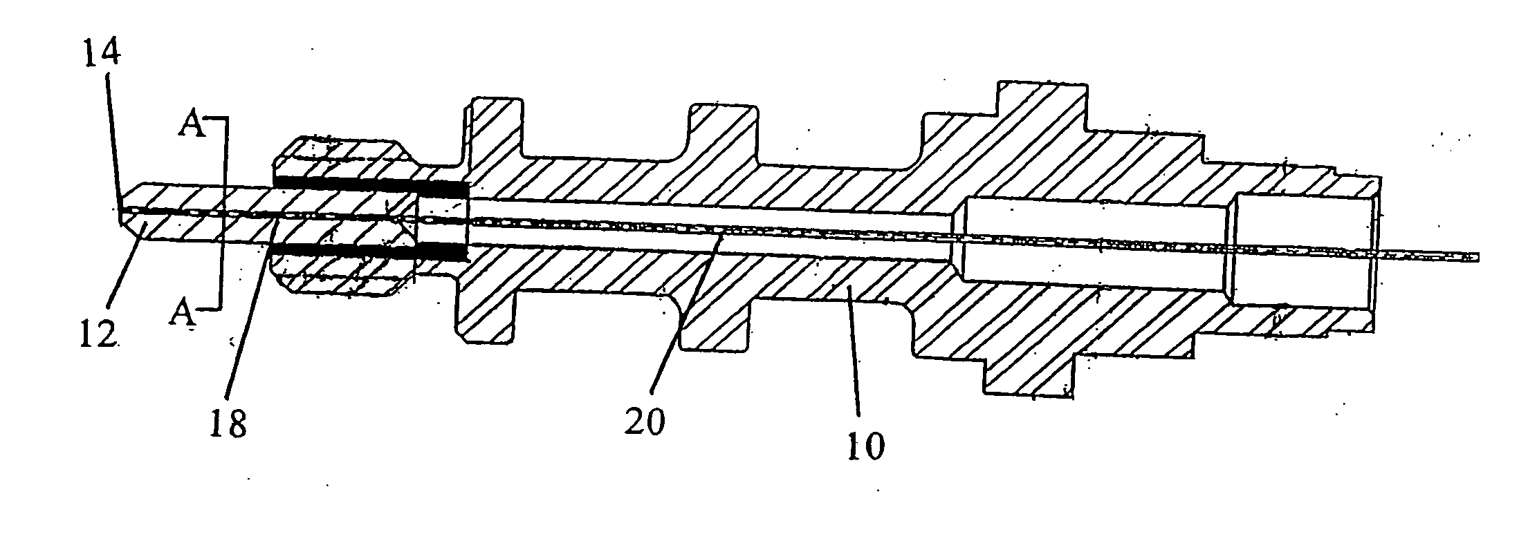
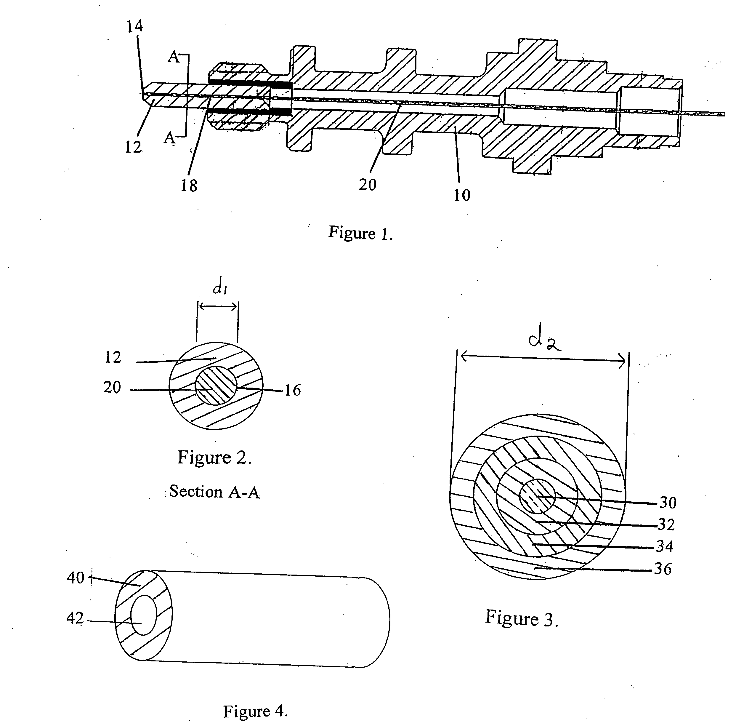
[0009] One embodiment of the present invention includes a glass-to-metal seal having an optical fiber having a metallized portion wherein the metallized portion has an outer dimension, and an object that includes a high strength, corrosion-resistant alloy, a bore extending therethrough, an inner surface defining the bore, and wherein a dimension of the inner surface is larger than the outer dimension of the metallized portion of the optical fiber, and a solder that includes a substance having a melting temperature greater than about 250° C., and wherein the solder is disposed between the metallized portion of the optical fiber and the inner surface of the object.
[0010] Further aspects of the present invention include wherein the object has a cross-sectional configuration which is generally cylindrical and the bore extends axially through the object; wherein the solder extends along the entire length of the inner surface of the bore of the object; wherein the optical fiber includes a glass fiber having a glass core with a protective coating on an outer surface of the glass core, and wherein the metallized portion includes an area of the glass core wherein the protective coating has been removed, and at least one metallic layer deposited on the area of the glass core; wherein the at least one metallic layer includes a metal selected from the group consisting of titanium, platinum, nickel, chromium, and mixtures and alloys thereof; wherein the at least one metallic layer includes an outermost layer including gold; wherein the solder includes a eutectic gold and tin material; wherein the eutectic gold and tin material includes about 80% by weight gold and about 20% by weight tin; wherein the metallized portion includes a layer of gold, a layer of platinum, and a layer of titanium; wherein the gold layer has a thickness of about 600 to about 1,100 Angstroms, the platinum layer has a thickness of about 3,600 to about 4,400 Angstroms, and the titanium layer has a thickness of about 100 to about 400 Angstroms; wherein the outermost layer is gold and the platinum layer is disposed between the gold layer and titanium layer; wherein the gold layer has a thickness of about 700 to about 1,100 Angstroms, the platinum layer has a thickness of about 3,800 to about 4,100 Angstroms, and the titanium layer has a thickness of about 150 to about 300 Angstroms; wherein the outermost layer is gold and the platinum layer is disposed between the gold layer and titanium layer; wherein the metallized portion includes a layer of gold, and a layer of chromium; wherein the gold layer has a thickness of about 600 to about 1,100 Angstroms, and the chromium layer has a thickness of about 500 to about 800 Angstroms; wherein the outermost layer is gold; wherein the high strength, corrosion-resistant alloy includes an alloy of nickel and chromium; wherein at least a portion of the inner surface of the object is gold plated; wherein at least a portion of the inner surface of the bore is gold-plated; wherein the solder is subjected to a stress relief treatment includes a temperature cycling process; wherein the temperature cycling process includes heating the seal to about 200° C., cooling the seal to about −40° C., and heating the seal to about 200° C.; wherein the temperature cycling process is repeated at least once; and wherein the seal is held at each temperature in the cycling process for about an hour.
[0011] Another embodiment of the present invention includes a glass-to-metal seal including an optical fiber having a glass core with a protective coating on an outer surface of the glass core, and a metallized portion, the metallized portion having an outer dimension, including an area of the glass core wherein the protective coating has been removed, and one or more metallic layers deposited on the area of the glass core, wherein at least one of the one or more metallic layers including a metal selected from the group consisting of titanium, platinum, nickel, chromium, and mixtures and alloys thereof, and at least one of the one or more metallic layers includes an outermost layer including gold, an object including a cross-sectional configuration which is generally cylindrical having a high strength, corrosion-resistant alloy of nickel and chromium, the object having a bore extending axially through the housing, an inner surface with a dimension larger than the outer dimension of the metallized portion of the optical fiber, and wherein at least a portion of the inner surface of the housing is gold plated, and a solder including about 80% by weight gold, about 20% by weight tin, and wherein the solder is disposed between the metallized portion of the optical fiber and the inner surface of the housing, such that a hermetic seal is provided between the metallized portion of the optical fiber and the inner surface of the housing, and wherein the solder has been subjected to a stress relief treatment including a temperature cycling process.
[0012] Yet another embodiment of the present invention includes a method for providing a glass-to-metal seal for high-pressure / high-temperature, downhole environments, the method includes (a) providing an optical fiber having a metallized portion, the metallized portion having an outer dimension, (b) providing a housing that includes a high strength, corrosion-resistant alloy and having a bore extending therethrough, the housing having an inner surface defining the bore with a dimension larger than the outer dimension of the metallized portion of the optical fiber, (c) positioning the metallized portion of the optical fiber within the bore, and (d) forming a hermetic, hardened solder seal between the metallized portion of the optical fiber and the inner surface of the housing, wherein the solder seal includes a eutectic gold and tin material.
[0013] Further aspects of the present embodiment include wherein the housing has a generally cylindrical cross-sectional configuration and the bore extends axially through the housing; wherein the high strength, corrosion-resistant alloy includes an alloy of nickel and chromium; wherein at least a portion of the inner surface of the housing is gold plated; wherein at least a portion of the inner surface of the housing is gold plated; providing an optical fiber which includes a glass fiber having a glass core with a protective coating disposed on an outer surface of the glass core, removing a portion of the protective coating, and depositing one or more metallic layers on the portion of the glass core where the protective coating has been removed to form the metallized portion of the optical fiber; wherein at least one of the one or more metallic layers includes a metal selected from the group consisting of titanium, platinum, nickel chromium, and mixtures and alloys thereof, and at least one of the one or more metallic layers includes an outermost layer including gold; wherein the gold in the eutectic gold and tin material is present in an amount of about 80% by weight and the tin is present in an amount of about 20% by weight; the step of subjecting the solder seal to a stress relief treatment including a temperature cycling process; wherein the temperature cycling process includes heating the seal to about 200° C., cooling the seal to about −40° C., and heating the seal to about 200° C.; wherein the temperature cycling process is repeated at least once; and wherein the seal is held at each temperature in the cycling process for about an hour.
[0014] A further embodiment of the present invention includes a downhole optical feedthrough including a seal produced according to the method of (a) providing an optical fiber having a metallized portion, the metallized portion having an outer dimension, (b) providing a housing including a high strength, corrosion-resistant alloy and having a bore extending therethrough, the housing having an inner surface defining the bore with a dimension larger than the outer dimension of the metallized portion of the optical fiber, (c) positioning the metallized portion of the optical fiber within the bore, and (d) forming a hermetic, hardened solder seal between the metallized portion of the optical fiber and the inner surface of the housing, wherein the solder seal includes a eutectic gold and tin material.

