Method of removing a photoresist pattern and method of manufacturing a semiconductor device using the same

Inactive Publication Date: 2006-11-30
SAMSUNG ELECTRONICS CO LTD
View PDF6 Cites 3 Cited by
  • Summary
  • Abstract
  • Description
  • Claims
  • Application Information

AI Technical Summary

Benefits of technology

[0030] According to an example embodiment of the present invention, no residual photoresist pattern may remain on the lower electrode to thereby reduce electrical resistance of a capacitor due to the residual photoresist pattern and improve cap

Problems solved by technology

Thus, a pad, which is electrically connected to the lower electrode, may be deteriorated.
However, the photoresist film may not be easily removed by a conventional process.
The remaining photoresist film in the opening may not be easily removed by a conventional ashing process so that the remaining photoresist film may work as a resistor to cause an operation failure of a capacitor in a semiconductor device.
In order to increase efficiency of removing the sacrificial layer in the opening, an oxygen plasma ashing process may be carried out at a relatively high temperature of about 150° C. to about 250° C. However, the lower electrode may be damaged or oxidated by the ashing process because of the relatively

Method used


Image

  • Method of removing a photoresist pattern and method of manufacturing a semiconductor device using the same
  • Method of removing a photoresist pattern and method of manufacturing a semiconductor device using the same
  • Method of removing a photoresist pattern and method of manufacturing a semiconductor device using the same

Examples


Embodiment Construction

[0036] Various example embodiments of the present invention will now be described more fully with reference to the accompanying drawings, in which some example embodiments of the present invention are shown. Example embodiments of the present invention may, however, be embodied in many different forms and should not be construed as limited to the example embodiments set forth herein. Rather, these example embodiments are provided so that this disclosure will be thorough and complete, and will fully convey the scope of the present invention to those skilled in the art. In the drawings, the sizes and relative sizes of layers and regions may be exaggerated for clarity.

[0037] It will be understood that when an element or layer is referred to as being “on,”“connected to” or “coupled to” another element or layer, it can be directly on, connected or coupled to the other element or layer or intervening elements or layers may be present. In contrast, when an element is referred to as being ...


PUM

PropertyMeasurementUnit
Temperatureaaaaaaaaaa
Densityaaaaaaaaaa

Abstract

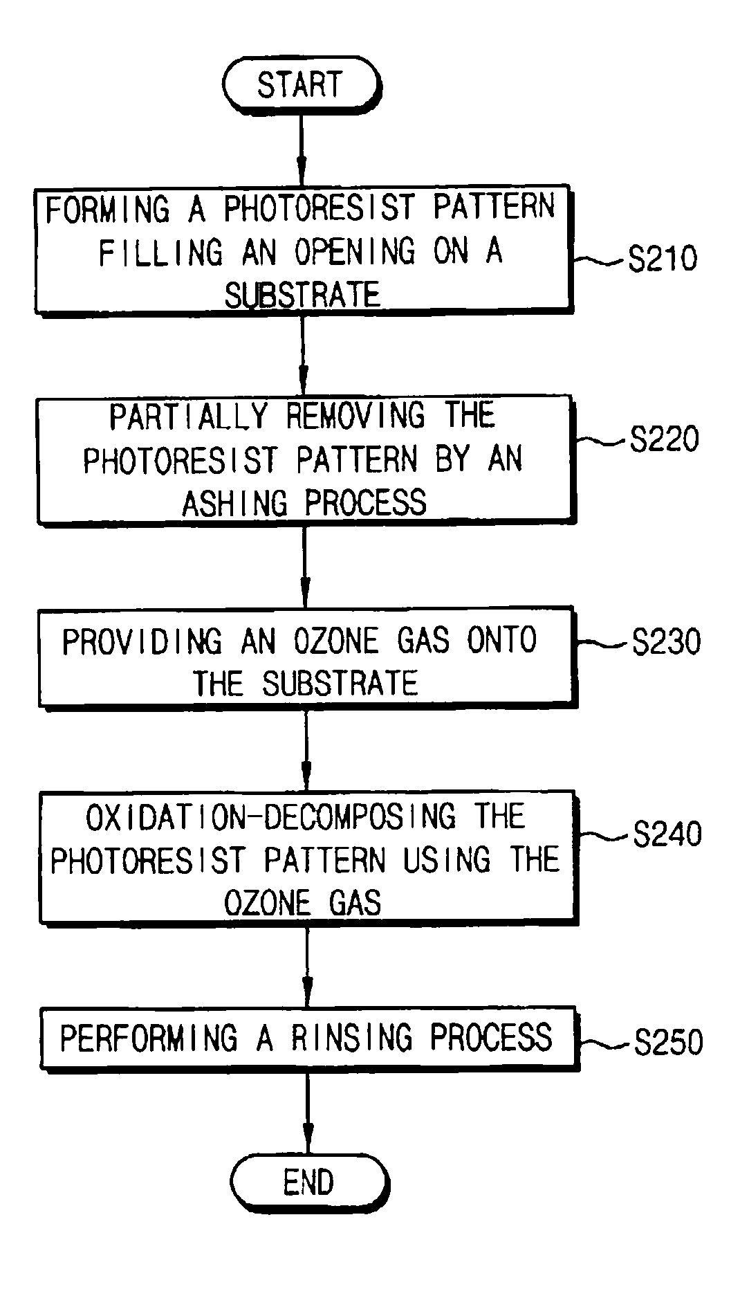
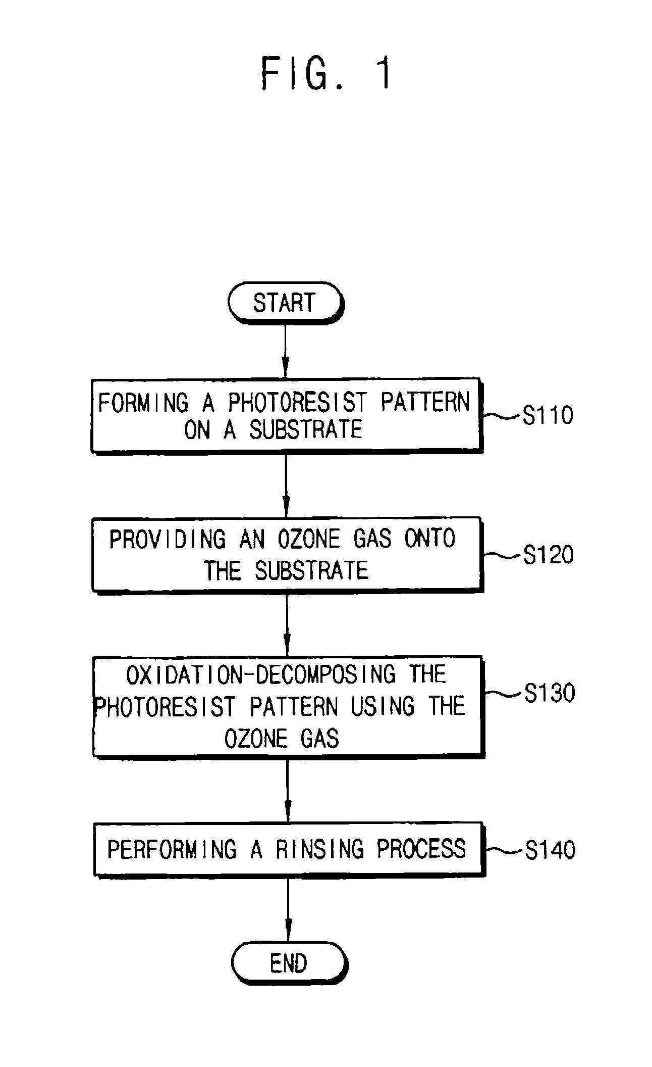
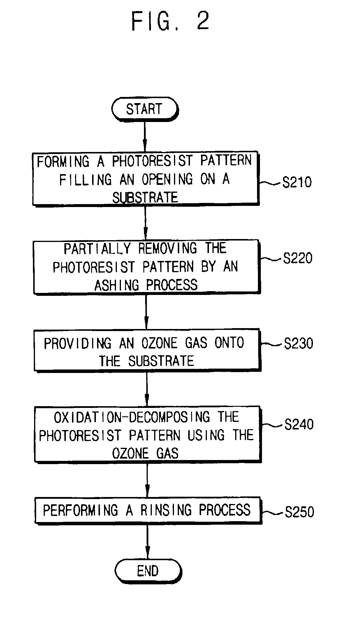
In a method of removing a photoresist pattern from a substrate without deteriorating a lower electrode or increasing processing time, ozone gas may be provided onto a substrate on which a photoresist pattern may be formed. An oxidation-decomposition process may be carried out using the ozone gas, to thereby decompose the photoresist pattern on the substrate. The decomposed photoresist pattern may be dissolved into water and removed from the substrate in a rinsing process. Accordingly, a photoresist pattern in an opening having a relatively high aspect ratio may be sufficiently removed from a substrate without deteriorating the lower electrode or increasing processing time.

Description

PRIORITY STATEMENT [0001] This application claims priority under 35 U.S.C. § 119 to Korean Patent Application No. 2005-45385 filed on May 30, 2005, in the Korean Intellectual Property Office (KIPO), the entire contents of which are herein incorporated by reference. BACKGROUND [0002] 1. Field [0003] Example embodiments of the present invention relate to a method of removing a photoresist pattern, for example, a method of removing a photoresist pattern remaining in an opening, and a method of manufacturing a semiconductor device using the same, for example, a method of manufacturing a semiconductor device having a lower electrode using the same. [0004] 2. Description of the Related Art [0005] Recently, an integration degree of a dynamic random access memory (DRAM) device has increased up to a gigabyte scale so that the allowable space per a cell of the DRAM device has continuously decreased. Accordingly, a conventionally flat-shaped capacitor now may have various structures such as a ...

Claims


Application Information

Patent Timeline
IPC IPC(8): B08B3/00C23G1/00H01L21/302
CPCB08B7/00B08B7/0035H01L28/91H01L21/31138G03F7/427H10B99/00
Inventor KIM, KYOUNG-CHULKANG, DAE-KEUNCHA, SE-HOHWANG, IN-SEAKLEE, KEUM-JOO
Owner SAMSUNG ELECTRONICS CO LTD
Why Eureka
Try Eureka