Examples include the desire to “compute an average of readings taken by 10 different temperature sensors,” or to “compute the minimum out of 30 distinct
humidity sensor readings.”
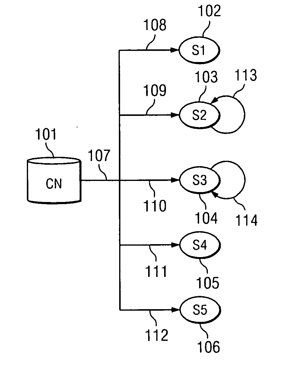
Scalability is a major technical challenge in such future networks, which are projected to contain thousands, and possibly hundreds of thousands, of tiny sensor nodes deployed fairly densely over the sensing field.
A key characteristic of many such operating environments is that such networks often exhibit significant redundancy, in that most applications do not normally require the use of sensor data from all of the available sensor nodes.
Indeed, the
physical density of sensor networks may often vary greatly over the sensing field due to choice (e.g., network designers may deploy more nodes in an area where finer location accuracy is required), lack of precise control (e.g., when nodes over a remote
terrain are deployed by being dropped from an
airplane), or failures (e.g., when sets of sensor nodes turn out to be defective or die due to exhaustion of battery resources).
The main challenge in supporting such energy-efficient operation is that, while applications may be able to express the amount of resources (such as the number or resolution of the sensor nodes), they typically have no idea of the actual number or
layout of the sensors deployed.
Accordingly, an application may not be able to decide on the appropriate settings (e.g., on or off, high or low
zoom) for each individual sensor.
However, such a mechanism is not useful in future sensor network environments for two distinct reasons.
For example, the sensor network substrate can be modified either due to the occasional addition of new nodes, the death or removal of existing nodes and due to other unforeseen reasons (such as catastrophic node failures).
This imposes a substantial reporting overhead and cannot scale to large sensor network environments, since every such change in the
network topology must be propagated to the
database.
If a static configuration scheme is employed instead, it may quickly become inappropriate for the given
operating environment.
Although all of these techniques define “how” some queries or requests are propagated over the sensing field, these techniques do not define “what” is propagated or how individual nodes respond to the “what” they receive.
Moreover, they do not define or provide an
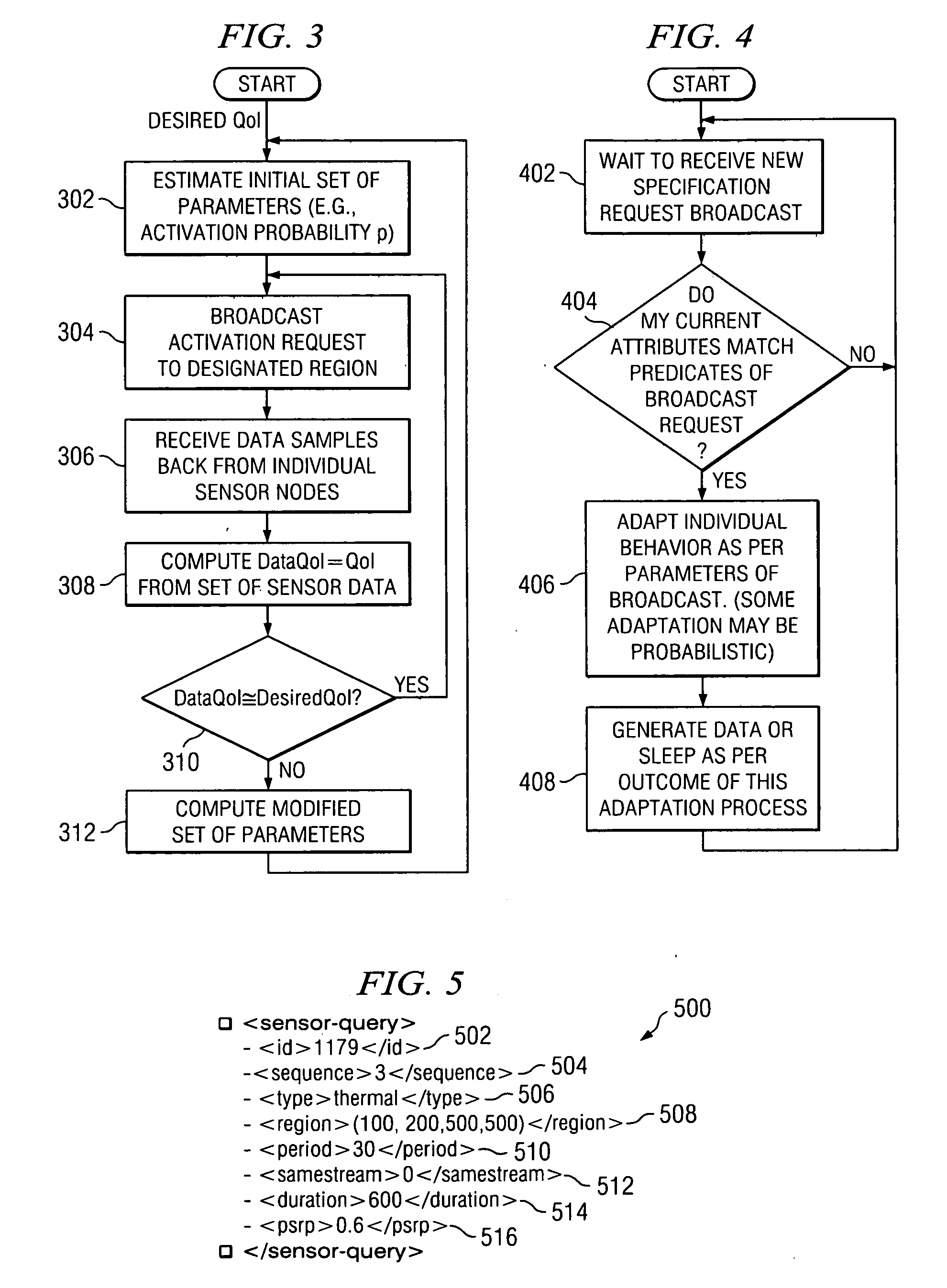
adaptive method by which the “what” (i.e., the content) may be used to continually meet the QoI requirements of the application, even though the topology and other physical properties of the sensor network changes.
However, DD does not provide a method by which the application's QoI requirements can be met by iteratively issuing directed broadcasts, with modifications to the parameters contained in the broadcast.
However, like DD, the AR technique does not propose the use of an iterative mechanism to match the amount and quality of sensor data to an application's QoI requirements, thereby avoiding redundant operation of sensor nodes.
However, all of the proposals and prior art in this domain deal with mechanisms by which nodes get to know of this probability, and not with methods by which such probabilities can be used to iteratively control the collective behavior of a set of sensor nodes.
However, these approaches do not utilize a control loop for adjusting the probability to the “right level” desired by the controller, and do not talk about using the probabilities or other parametric values to adjust other behaviorial parameters (such as
data reporting frequency or camera
zoom level) of a subset of the sensor nodes.
However, in LEACH, there is no notion of a control loop being used by a gateway node to dynamically tune the value p to ensure that it meets a target value N. Moreover, LEACH does not utilize broadcasts from a gateway node that are targeted to a specific sub-set of the sensor nodes (identified for example by the type or location of the sensor nodes) to activate varying numbers of sensors with different attributes (e.g., type or location).
They do not provide a method of dynamically controlling the activation probabilities without knowing the node density (and for non-uniform node densities), or discuss a broadcast-based technique to activate the right number of sensors without addressing them individually.

